background image

Chapter 1 – Product Overview 

13 

Siemens Industry, Inc. 

BACnet ATEC Owner's Manaul 

125-5050, Rev. AA 


4/20/2010 

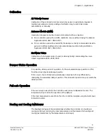
Temperature Sensors 

Room Temperature Sensor 

The controller room temperature sensor connects to the controller by means of a cable 

terminated at both ends with a six-conductor RJ-11 plug-in connector. 

Duct Temperature Sensor 

An optional duct temperature sensor provides duct air temperature sensing inputs to 

the controller. 
For more information about temperature sensors, contact your local Siemens Industry 

representative. 

Related Equipment 


Autozero Module (optional) 540-200 


Relay Module 


Damper Actuator(s) 


Duct Temperature Sensor (optional) 


Room Temperature Sensor  

Contact your local Siemens Industry representative for product numbers and more 

information. 

Содержание BACnet ATEC

Страница 1: ...Siemens Industry Inc 125 5050 Rev AA Siemens BACnet ATEC Owner s Manual ...

Страница 2: ...and in the subject thereof By acceptance of the document the recipient acknowledges these rights and undertakes not to publish the document nor the subject thereof in full or in part nor to make them available to any third party without our prior express written authorization nor to use it for any purpose other than for which it was delivered to him ...

Страница 3: ...e at their own expense Service Statement Control devices are combined to make a system Each control device is mechanical in nature and all mechanical components must be regularly serviced to optimize their operation Siemens Industry Inc branch offices and authorized distributors offer Technical Support Programs that will ensure continuous trouble free system performance For further information con...

Страница 4: ...enna Increase the separation between the equipment and receiver Connect the equipment into an outlet on a circuit different from that to which the receiver is connected Consult the dealer or an experienced radio TV technician for help To the Reader Your feedback is important to us If you have comments about this manual please submit them to mailto Sbt_technical editor us sbt siemens com Credits AP...

Страница 5: ...tion 15 Heating and Cooling Switchover 15 Modulate Damper During Heating Mode optional 16 Hot Water Reheat 16 Electric Reheat 16 Notes 16 Application 2860 VAV Cooling Only 17 Application 2861 VAV Cooling or Heating 17 Application 2862 VAV with Electric Reheat or Baseboard Radiation 17 Baseboard Radiation 18 Electric Heat Interlock 18 Application 2863 VAV with Hot Water Reheat 18 Application 2864 V...

Страница 6: ...l 125 5050 Rev AA 4 20 2010 Using the Controller as a Point Extension Device 22 Chapter 3 Point Database 24 Chaper 4 Troubleshooting 30 Basic Service Information 30 Preventive Maintenance 30 Safety Features 31 Controller LEDs 31 Glossary 32 Index 35 ...

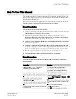
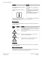
Страница 7: ...er a problem when using the BACnet VAV Actuator For issues not covered in this chapter consult your local Siemens Industry representative The Glossary describes the terms and acronyms used in this manual The Index helps you locate information presented in this manual Manual Conventions The following table lists conventions to help you use this manual in a quick and efficient manner Convention Exam...

Страница 8: ...table lists the safety symbols used in this manual to draw attention to important information Symbol Meaning Description NOTICE CAUTION Equipment damage may occur if a procedure or instruction is not followed as specified For online documentation the NOTICE displays in white with a blue background CAUTION Minor or moderate injury may occur if a procedure or instruction is not followed as specified...

Страница 9: ...of the controller and the mounting bracket Table 1 lists the BACnet ATEC products that are covered Table 1 BACnet ATEC Electronic Output Applications Application Number Application Description 2860 VAV Cooling Only 2861 VAV Cooling or Heating 2862 VAV with Electronic Reheat or Baseboard Radiation 2863 VAV with Hot Water Reheat 2864 VAV Series Fan Powered with Electric Reheat 2865 VAV Series Fan Po...

Страница 10: ...Rev AA 4 20 2010 Siemens BACnet ATEC Hardware Inputs Analog Air Velocity Sensor AVS Duct temperature sensor optional Application 2861 Room temperature sensor RTS Room temperature setpoint dial optional Digital Night mode override optional Wall switch optional Hardware Outputs Analog None ...

Страница 11: ... or 2 position heating valve 2862 Stage 1 electric reheat 2864 2866 Stage 2 electric reheat optional 2862 2864 2866 Stage 3 electric reheat optional 2862 Valve actuator 2865 2867 Power Wiring The controller is powered by 24 Vac Power wiring connects to the two screw terminals on the controller labeled C Common and H Hot on the terminal block labeled 24 VAC No earth ground connection is required Se...

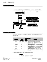
Страница 12: ...gure Siemens BACnet ATEC Controller LEDs LED Type Label if present LED Number Indication DO LED 3 LED 5 3 5 Indicates the ON OFF status of the DO associated with it A glowing LED indicates that the DO is energized Transmit TX 0 Indicates when flashing that the controller is transmitting information to the field panel Receive RX 1 Indicates when flashing that the controller is receiving information...

Страница 13: ...or RJ 11 plug in connector Duct Temperature Sensor An optional duct temperature sensor provides duct air temperature sensing inputs to the controller For more information about temperature sensors contact your local Siemens Industry representative Related Equipment Autozero Module optional 540 200 Relay Module Damper Actuator s Duct Temperature Sensor optional Room Temperature Sensor Contact your ...

Страница 14: ...le Control Temperature Setpoints The controller maintains a specified temperature setpoint based on Day Night mode or the heating cooling mode or the setpoint dial if used Day Night Mode The controller maintains the specified day setpoint temperature during daytime hours and the specified night setpoint at night Night Mode Override Switch If the ROOM TEMPERATURE SENSOR has an override switch it ca...

Страница 15: ...hot water valve if used is done by briefly commanding the valve closed Application 2863 2865 2867 Damper Status Operation It is possible after a period of operation for the calculated damper position to differ from the actual physical damper position If this occurs the controller will automatically compensate for any difference by readjusting the calculated damper position This calculated position...

Страница 16: ...closed The heating loop modulates the heating valve s to warm up the room In cooling mode the heating valve is closed Electric Reheat CAUTION Verify that the equipment is supplied with safeties by others to ensure that there is airflow across the heating coils when they are to be energized The heating loop controls up to three stages of electric reheat to warm up the room The electric reheat is ti...

Страница 17: ...In Application 2861 the controller modulates the supply air damper of the terminal box for cooling and heating In order for it to work properly the central air handling unit must provide cool supply air in cooling mode and warm air during heating mode See the following figure Application 2862 VAV with Electric Reheat or Baseboard Radiation In Application 2862 the controller modulates the supply ai...

Страница 18: ...mum to less than 5 otherwise the electric heat interlock will be disabled The electric heat stages will be disabled turned off when the electric heat airflow is less than the defined minimum Application 2863 VAV with Hot Water Reheat In Application 2863 the controller modulates the supply air damper of the terminal box for cooling and controls a hot water valve or baseboard radiation for heating W...

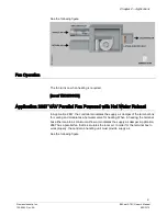
Страница 19: ... supply air damper Application 2864 has a series fan for air circulation In order for the terminal box to work properly the central air handling unit must provide supply air See the following figure Fan Operation CAUTION On series fan powered terminal boxes the terminal box fan must be controlled interlocked to start either before or at the same time as the central air handler Failure to do so may...

Страница 20: ...owered terminal boxes the terminal box fan must be controlled interlocked to start either before or at the same time as the central air handler Failure to do so may cause the terminal box fan to rotate backwards and cause consequent damage at start up In day mode the fan is ON all the time In night mode the fan cycles on when heating or cooling is required Application 2866 VAV Parallel Fan Powered...

Страница 21: ...Water Reheat In Application 2867 the controller modulates the supply air damper of the terminal box for cooling and modulates a hot water valve for heating When in heating the terminal box either maintains minimum airflow or modulates the supply air damper Application 2867 has a parallel fan that re circulates the room air In order for the terminal box to work properly the central air handling uni...

Страница 22: ...er parameters CTLR ADDRESS APPLICATION etc A controller in default state can also be used as a point extension device by unbundling spare I O points at the field panel Using Auxiliary Points It is possible to have extra points available on a BACnet VAV Controller Electronic Output in addition to the ones used by the current application that is running in the controller If these extra points are to...

Страница 23: ... control a motor as shown in the example NOTE If using either a motor or DOs as auxiliary points be sure to set MTR SETUP to the correct value If using a pair of DOs to control a motor then the DOs cannot be unbundled Only MTR COMD can be unbundled to control the motors Contact your local Siemens Industry representative for other combinations of DOs and motors ...

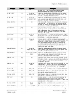
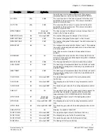
Страница 24: ...TPT 08 All except 2597 The temperature setpoint in degrees that the controller maintains during the night periods in cooling mode NGT HTG STPT 09 All except 2560 2597 The temperature setpoint in degrees that the controller maintains during the night periods in heating mode RM STPT MIN 11 All except 2597 The minimum temperature setpoint in degrees that the controller can use from the setpoint dial ...

Страница 25: ...e switch has been pressed and the override timer is active The controller then uses a day mode temperature setpoint This point is only in effect when DAY NGT indicates night mode REHEAT START 22 All except 2560 2561 2597 Determines how the reheat modulation will be sequenced while in heating mode When HTG LOOPOUT is above this value then the reheat modulates upward REHEAT END 23 All except 2560 25...

Страница 26: ...tal output 5 controls a 24 Vac load with an ON or OFF status If Motor 3 is enabled DO 5 is coupled with DO 6 to control an actuator DO 5 45 2565 2567 Digital output 5 controls a 24 Vac load with an ON or OFF status HEAT STAGE 3 45 2 2562 2564 2566 This point is a digital output used to control the contact for the third stage of heating and has a status of ON or OFF FAN 46 2564 2565 2566 2567 This ...

Страница 27: ...energized EHEAT FLOW 60 2562 The flow required before the electric heat will be enabled COOL TEMP 61 2561 The discharge air temperature where the controller will switch from heating to cooling mode Used only in applications with SUPPLY TEMP HEAT TEMP 62 2561 The discharge air temperature where the controller will switch from cooling to heating mode Used only in applications with SUPPLY TEMP CLG P ...

Страница 28: ...ric heat With electric heat this value is equal to HTG LOOPOUT STAGE COUNT STAGE MAX 82 2562 2564 2566 The value in percent which the heating loop must exceed for the electric heat to be ON for the full duty cycle STAGE TIME STAGE FAN 83 2565 2567 The valve must be opened greater than this value before the fan will turn ON STAGE MIN 83 2562 2564 2566 The value in percent which the heating loop mus...

Страница 29: ...s of the duct where the air velocity sensor is located This is a calculated value calculated by the field panel or computer being used that depends on duct shape and size It is used in calculating all points in units of CFM CF LPS and L Valid input 025 ft2 002 m2 through 6 375 ft2 5923 m2 LOOP TIME 98 All except 2597 The time in seconds between control loop calculations ERROR STATUS 99 2 All The s...

Страница 30: ...ller is to turn OFF the power to the 24 Vac transformer The recommended method of removing power to a controller on a power cable even to service a single controller is to turn OFF the power at the transformer NOTE When removing power to a controller to perform maintenance or service make sure that the person in charge of the facility is aware of this and that appropriate steps are taken to keep t...

Страница 31: ...ller will activate safety features present in its fail safe mode Sensor failure Loss of power Upon controller power loss communication with the controller is also lost The controller will appear as failed F at the field panel Controller LEDs NOTE The TX and RX LEDs indicate communication over the FLN To determine if the controller is powered up and working verify that the Basic Sanity Test BST Lig...

Страница 32: ...e an output value AVS Air Velocity Sensor centralized control Type of control offered by a controller that is connected by means of Field Level Network FLN cfm Cubic Feet per Minute control loop PID algorithm that is used to control an output that is based on a setpoint and an input reading from a sensor DDC Direct Digital Control DO Digital Output Physical output point that sends a two state sign...

Страница 33: ...ws you to communicate with a field panel or equipment controller override switch Button on a room temperature sensor that an occupant can press to change the status of a room from unoccupied to occupied or from night to day for a predetermined time pressure independent Variable Air Volume VAV room temperature control system in which the temperature drives an airflow setpoint PID Proportional Integ...

Страница 34: ...nic Output that house the applications software used to control terminal units such as heat pumps VAV terminal boxes fan coil units unit ventilators etc UI Universal Input Can be used as an AI or DI An AI input is a point receiving a signal that represents a condition that has more than two states A DI input is a physical input point that receives a two state signal unbundle Term used to describe ...

Страница 35: ...rawing 19 electric heat 20 electric heat interlock 20 overview 19 application 2863 control drawing 20 overview 20 application 2864 overview 21 application 2865 overview 22 Application 2865 fan operation 22 application 2866 overview 23 application 2867 overview 23 Application 2897 overview 24 using controller as point extension device 24 applications calibration 17 27 control loops 16 control tempe...

Страница 36: ... H hardware autozero module 17 fan 11 13 21 22 23 24 LEDs 14 power wiring 13 relay module 15 temperature sensors 15 L Light Emitting Diodes LEDs 32 BST 32 RX and TX 32 loopout 34 O override switch 34 P PID 34 point database overview 25 power wiring 13 preventive maintenance 31 R related equipment 15 relay module 15 RTS 34 RX LED 32 S safety features 32 service information basic 31 SI units 34 stan...

Страница 37: ...Index 37 Siemens Industry Inc BACnet ATEC Owner s Manaul 125 5050 Rev AA 4 20 2010 W wiring communication wiring 14 power wiring 13 ...

Страница 38: ...eerfield Parkway Buffalo Grove IL 60089 USA Tel 1 847 215 1000 2010 Copyright Siemens Industry Inc Technical specifications and availability subject to change without notice Document ID 125 5050 Rev AA Manual Siemens BACnet ATEC Owner s Manual Edition 4 20 2010 Register ...

Отзывы: