background image


English •


5

Saf
e

ty Ins

tructions

Pr

eparation

Ins
tallation

Final S

teps

Step 5 and 6: Install Oven and Test Operation

5. Install Oven

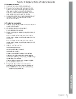
1.  Slide oven into cabinet cutout.
2.  Push straight in until oven trim is fl ush with   


cabinet  wall, being careful not to crimp fl exible con-   


duit between oven and cabinet back wall. The oven   


should be straight, not crooked.

3

.  Install screws (two or four depending on model) 


through tap holes in trim.

6. Test Operation 

1.  Verify that all control knobs are in the OFF position.
2.  Turn on power at the breaker.
 

The clock will appear in the display. 

3.  Check power at junction box using a volt meter. 
 

For 240 V installation, the reading between the red    


and black wires (line to line) should be 220 to 240    


volts.


For 208 V installation, the reading between the red    


and black wires (line to line) should be 190 to 208    


volts.

4.  Test the oven mode.
 

Press COOKING MODE.


Turn knob to BAKE. 


Touch START.
PREHEAT appears in display.


When the oven has reached the set temperature  


(350° F), it beeps and PREHEAT no longer appears. 


If installing a double oven, test the second oven as    


well. 

5.  If any of the tests do not result as explained above,   


contact Siemens service: 866-44-SIEMENS. Other 


wise, the installation is complete at this time.

Содержание avantGarde SKU HB30D50U

Страница 1: ...talación para el horno Models HB30S50U HB30D50U Please read instructions before using Important Save these instructions Merci de lire instructions avant utilisation Important Conserver ces instructions Por favor lee los instrucciones antes del uso Importante Guarda esos instrucciones ...

Страница 2: ......

Страница 3: ...rized repair service Know how to disconnect the power to the oven at the circuit breaker or fuse box in case of an emergency Do not repair or replace any part of the appliance unless specifically recommended in the manuals All other servicing should be done by a qualified technician This may reduce the risk of personal injury and damage to the oven Never modify or alter the construction of an oven b...

Страница 4: ...tch must be increased to handle the electrical load demanded by the oven Verify that wiring inside house is adequate Most wiring codes require a separate circuit with sepa rate disconnect switch and fuses either in the main entrance panel or in a separate switch and fuse box Most local building regulations and codes require that electrical wiring be done by licensed electricians Be sure to install...

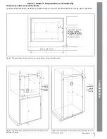
Страница 5: ...nglish 3 Safety Instructions Preparation Installation Final Steps Figure 1 Single Oven Under Counter Cutout Dimensions Electrical supply junction box D A B C F E Electrical supply junction box B A E C F ...

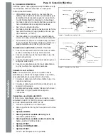
Страница 6: ...en ground wire from oven to green or bare ground wire in junction box 2 Connect red wire from oven to red wire in junction box 3 Connect black wire from oven to black wire in junction box 4 Connect white wire from oven to white or gray neutral wire in junction box Three Wire Connection Note The four wire connection is preferred but where local codes permit the three wire connection is also accepta...

Страница 7: ...t the breaker The clock will appear in the display 3 Check power at junction box using a volt meter For 240 V installation the reading between the red and black wires line to line should be 220 to 240 volts For 208 V installation the reading between the red and black wires line to line should be 190 to 208 volts 4 Test the oven mode Press COOKING MODE Turn knob to BAKE Touch START PREHEAT appears ...

Страница 8: ...Safety Instructions Preparation Installation Final Steps ...

Страница 9: ...aut savoir comment débrancher l alimentation du four au coupe circuit ou à la boîte de fusible en cas d urgence Ne pas remplacer ni réparer toute pièce de l appareil sauf si spécifiquement recom mandé dans les guides Tout autre service doit être effectué par un technicien qualifié Ceci peut réduire tout risque de dommage au four ou de blessures Ne jamais modifier la construction du four en enlevant l...

Страница 10: ...port du four doit être d au moins 3 4 po d épaisseur plateforme en contreplaqué pouvant supporter 150 lb Pour four double pour supporter 290 lb Elle doit être robuste de niveau et à égalité avec le bas de la découpe de l armoire Dimensions de la découpe de l armoire Voir tableau 1 ci dessous et les figures 1 2 et 3 à la page suivante pour les dimensions de découpe Étapes 1 à 3 préparation Vérifier s...

Страница 11: ...armoire adjacente ou en dessous de la surface de support inférieur B A E C F Boîte de jonction d alimentation électrique Figure 2 four mural simple ou dimensions de découpe de l armoire Figure 3 four mural double ou dimensions de découpe de l armoire Étapes 1 à 3 préparation suite Dimensions de découpe de l armoire Consulter les figures ci dessous et le tableau à la page précédente concernant les d...

Страница 12: ...ble d alimentation élec trique La connexion du circuit terminal à 4 fils est recom mandée mais là où les codes le permettent une connexion de circuit terminal à 3 fils est acceptable Étape 4 connexion électrique Connexion à 4 fils recommandée 1 Brancher le fil de mise à la terre vert du four sur le fil de mise à la terre vert ou dénudé de la boîte de jonction 2 Brancher le fil rouge du four sur le fil ro...

Страница 13: ...tion en circuit au coupe circuit La pendule figure à l affichage 3 Vérifier l alimentation à la boîte de jonction à l aide d un voltmètre Pour installation 240 V la lecture entre les fils noir et rouge ligne à ligne doit être 220 et 240 volts Pour installation 208 volts la lecture entre les fils noir et rouge ligne à ligne doit être 190 et 208 volts 4 Vérifier le mode four Presser COOKING MODE Tourner l...

Страница 14: ...Instructions de sécurité Préparation Installation Étapes fi nales ...

Страница 15: ...s códigos aplicables Instale solamente de acuerdo a las instrucciones de instalación que se incluyen en el paquete de literatura para este horno Pídale a su distribuidor que recomiende un técnico calificado y un centro de servicio autorizado Aprenda a desconectar la corriente al horno en el cortacircuitos o la caja de fusibles en caso de una emergencia No trate de reparar o reemplazar alguna parte ...

Страница 16: ...por el horno Verificar que el cableado adentro de la casa sea el adecuado La mayoría de los códigos de cableado requieren un circuito separado con un desconectador separado y fusibles en el panel principal de entrada o en una caja separada para el interruptor y para los fusibles La mayoría de las regulaciones locales de construcción requieren que un eléctrico calificado haga las instalaci La mayoría...

Страница 17: ...montar un solo horno en un gabinete o la pared Figura 3 Dimensiones de recorte para montar un doble horno en un gabinete o la pared Pasos 1 hasta 3 Preparación continuación Dimensiones de Recorte del Gabinete Consulte las figuras abajo y la tabla en la página anterior para ver las dimensiones del recorte para el gabinete Alimentación eléctrica del horno localice la caja de conexiones en el gabinete...

Страница 18: ...conexiones Conexión con tres hilos Nota La conexión del circuito con cuatro hilos es preferible pero donde los códigos locales lo permiten se acepta también una conexión con tres hilos 1 Conecte el cable rojo del horno al cable rojo en la caja de conexiones 2 Conecte el cable negro del horno al cable negro en la caja de conexiones 3 Conecte ambos cables verde y blanco del horno al cable blanco o g...

Страница 19: ...la corriente en el interruptor El reloj aparece en la pantalla 3 Revise la corriente en la caja de conexiones con un voltímetro Para una instalación de 240V la lectura entre los cables rojos y negros línea a línea debe ser 220 a 240 voltios Para una instalación de 208V la lectura entre los cables rojos y negros línea a línea debe ser 190 a 208 voltios 4 Verifique el modo del horno Oprima COOKING MO...

Страница 20: ...e United States for use in Canada Check with your local Canadian distributor or dealer BSH Home Appliances Corporation 5551 McFadden Avenue Huntington Beach CA 92649 For the most up to date critical installation dimensions by fax use your fax handset and call 702 833 3600 Use code 8030 5551 McFadden Avenue Huntington Beach CA 92649 800 944 2904 www siemens home com 9000075436 No ECO 10024 Rev A A ...

Отзывы: