7SR21 & 7SR22 Argus Installation Guide
©2010 Siemens Protection Devices Limited
Chapter 5 Page 3 of 22
List of Figures
Figure 3.1-1 Overall Dimensions (mm) and panel Drilling for Size E6 Epsilon case
(Typically 4.2 kg)..................................................................................................................6
Figure 3.1-2 Overall Dimensions (mm) and Panel Drilling for Size E8 Epsilon Case
(Typically 5.3 kg)..................................................................................................................6
Figure 4.1-1 E6 Standard Comms (USB Front Port, Rear RS485) (See Note 2) ....................................8
Figure 4.1-2 E6 St Additional Comms (IRIG-B, 2 x F.O. (ST Connectors)) ..............................8
Figure 4.1-3 E6 St Additional Comms (IRIG B + RS485) (See Note 2) ....................................9
Figure 4.1-4 E6 St Additional Comms (IRIG B + RS232) ..........................................................9
Figure 4.2-1 E8 Standard Comms (USB Front Port, Rear RS485) (See Note 2) ..................................10
Figure 4.2-2 E8 St Additional Comms (IRIG B, 2 x F.O. (ST Connectors)).............................10
Figure 4.3-1 E8 St Additional Comms (IRIG B + RS485) (See Note 2) ..................................11
Figure 4.3-2 E8 St Additional Comms (IRIG B + RS232) ........................................................11
Figure 5.1-1
Connection Diagram for 7SR21 Relay...............................................................................12
Figure 5.2-1
Connection Diagram for 7SR22 Relay...............................................................................13
Figure 6.1-1 RS485 Data Comms Connections Between Relays..........................................................14
Figure 6.3-1 Data Comms to Multiple Devices Using 7SG24 and F.O. Star Network ...........................15
Figure 6.3-2 Data Comms to Multiple Devices Using 7SG24 and F.O. Ring Network ..........................15
Figure 6.4-1 RS485 Data Comms Connections Between Relays..........................................................16
Figure 6.5-1 RS232 Data Comms Pin Connections...............................................................................16
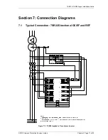
Figure 7.1-1 7SR22 Applied to Transformer Incomer ............................................................................17
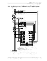
Figure 7.2-1 7SR22 Applied to Transformer Incomer Including HV NVD Protection.............................18
Figure 7.3-1 7SR22 Applied to Feeder Including NVD Protection .........................................................19
Figure 7.4-1 7SR22 Applied to Feeder ..................................................................................................20
Figure 7.5-1 7SR22 Applied to Feeder - No Zero Sequence Voltage Source .......................................21
Figure 7.6-1 7SR22 Applied to Feeder with Capacitor Cones Fitted .....................................................22


