65 / 92
Siemens
Actuators SAX.., SAY.., SAV.., SAL.. for valves
CE1P4040en
Building Technologies
Functions and control
2018-12-05
4.10 Detection of valve seat
The actuators feature force-dependent valve seat detection. After calibration, the
exact valve stroke is filed in the actuator’s memory. When the actuator reaches the
respective end of stroke, it does not hit the valve’s seat at full speed, but stops for 5
seconds at about 1% before the stored position is reached. If the positioning signal
stays at 0% or 100%, the actuator travels to the calculated end position at reduced
positioning speed and builds up the required nominal force.
This function extends the actuator’s service life since the dynamic forces are
reduced when approaching the valve seat and there will be less strain on the gear
train.
In addition, the actuator’s oscillations in the case of instable control are
suppressed.
If no force is built up in the calculated end position (e.g. in the event of temperature
effects for instance), the actuator continues to operate at a reduced positioning
speed until the nominal positioning force is restored. This ensures that the valve
always fully closes.
After a power failure, valve seat identification is not active – the actuators define
their stroke position on power resoration to be at 50%. From now on, the actuator
follows the positioning signal.
When the valve plug reaches its seat for the first time, the actuator readjusts its
stroke model.
The supposed position is 50%, Y = 2 V, the actuator travels 30% of the stored
valve stroke in the direction of "Actuator’s stem retracted".
If the actuator reaches the seat within this 30% travel, it interprets the position as
"Valve fully closed" and shifts the position of the valve’s stroke accordingly without
changing the extent of travel.
From now on, the actuator follows the changed valve stroke position.
This means: New position 0%, Y = 2 V, actuator travels 20% of the stored valve
stroke in the direction "Actuator’s stem extended".
4.11 Detection of foreign bodies
The actuator detects when the valve is clogged and adjusts its operational
behavior accordingly to prevent damage to itself or the valve.
If the actuator hits an obstacle within the calibrated stroke and is not able to
overcome it with its nominal positioning force, it stores the position at which the
obstacle was hit. Depending on the direction of travel, as …
·
"Lower limit of valve clogging", if the clogging was detected when
traveling in the direction of "Actuator’s stem retracting".
·
"Upper limit of valve clogging", if the clogging was detected when
traveling in the direction of "Actuator’s stem extending".
Now, the actuator status LED blinks green and the actuator only follows the
positioning signal between the positions "Actuator’s stem retracted" and "Upper
limit of valve clogging" or "Actuator’s stem extended" and "Lower limit of valve
clogging".
After detection of clogging, 3 attempts are made to overcome clogging by traveling
about 15% in the opposite direction and then trying again to overcome the position
of clogging. If the attempts made are unsuccessful, the actuator continues to follow
the positioning signal within the restricted range only and the actuator LED
continues to blink green (refer to "Indicators" on page 74).
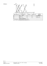
Example

