background image

56

Accessories, Sync Transceiver, Optical/Electrical Converter for Time Synchronization, Manual

C53000-G9050-C168-1, Edition 09.2019

Содержание 7XV5654-0BA00

Страница 1: ...r Elektrischer Umsetzer für die Zeitsyn chronisierung 7XV5654 0BA00 Handbuch C53000 G9050 C168 1 Vorwort Inhaltsverzeichnis Einführung 1 Aufbau des Gerätes 2 Anwendungsbeispiele 3 Montage und Inbetriebnahme 4 Technische Daten 5 Anhang A ...

Страница 2: ...nbart werden Dokumentversion C53000 G9050 C168 1 00 Ausgabestand 09 2019 Version des beschriebenen Produkts Copyright Copyright Siemens AG 2019 Alle Rechte vorbehalten Weitergabe sowie Vervielfältigung Verbreitung und Bear beitung dieses Dokuments Verwertung und Mitteilung des Inhaltes sind unzulässig soweit nicht schriftlich gestattet Alle Rechte für den Fall der Patenterteilung Geschmacks oder G...

Страница 3: ...eräten RoHS Richtlinie 2011 65 EU sowie elektrische Betriebsmittel zur Verwendung inner halb bestimmter Spannungsgrenzen Niederspannungsrichtlinie 2014 35 EU Diese Konformität ist das Ergebnis einer Bewertung die durch die Siemens AG gemäß den Richtlinien in Übereinstimmung mit den Fachgrundnormen EN 61000 6 2 und EN 61000 6 4 für die EMV Richtlinie der Norm EN 50581 für die RoHS Richtlinie und de...

Страница 4: ...ermeiden WARNUNG WARNUNG bedeutet dass Tod oder schwere Verletzungen eintreten können wenn die angegebenen Maßnahmen nicht getroffen werden Beachten Sie alle Hinweise um Tod oder schwere Verletzungen zu vermeiden VORSICHT VORSICHT bedeutet dass mittelschwere oder leichte Verletzungen eintreten können wenn die angege benen Maßnahmen nicht getroffen werden Beachten Sie alle Hinweise um mittelschwere...

Страница 5: ...nter gefährlicher Spannung Wenn nicht fachgerecht gehandelt wird können Tod schwere Verletzungen oder Sachschäden auftreten Das Betriebsmittel muss vor Anschluss von Verbindungen am Erdungsanschluss geerdet werden Gefährliche Spannungen können in allen mit der Spannungsversorgung verbundenen Schaltungsteilen anstehen Auch nach Abtrennen der Spannungsversorgung können gefährliche Spannungen im Betr...

Страница 6: ... 2002 96 EC über Elektro und Elektronikgeräte 10 Richtlinie für die eurasische Wirtschaftsunion Vorwort 6 Zubehör Sync Transceiver Optischer Elektrischer Umsetzer für die Zeitsynchronisierung Handbuch C53000 G9050 C168 1 Ausgabe 09 2019 ...

Страница 7: ...egung des T Adapterkabels 7XV5104 3AA00 21 3 Anwendungsbeispiele 23 3 1 Allgemein 24 3 2 Bis zu 6 SIPROTEC 4 SIPROTEC 5 Geräte synchronisieren 25 3 3 Bis zu 12 SIPROTEC 4 SIPROTEC 5 Geräte synchronisieren 26 3 4 Mehr als 12 SIPROTEC 4 SIPROTEC 5 Geräte synchronisieren 27 3 5 Bis zu 20 SIPROTEC 3 Geräte synchronisieren 29 3 6 Mehr als 20 SIPROTEC 3 Geräte synchronisieren 31 3 7 SIPROTEC 4 SIPROTEC ...

Страница 8: ...tedaten 48 5 2 Schnittstellen 50 5 3 Umgebungsbedingungen 51 5 4 Elektrische Prüfungen 52 5 5 Mechanische Prüfungen 53 A Anhang 55 A 1 Bestelldaten 56 A 2 Maße 57 Inhaltsverzeichnis 8 Zubehör Sync Transceiver Optischer Elektrischer Umsetzer für die Zeitsynchronisierung Handbuch C53000 G9050 C168 1 Ausgabe 09 2019 ...

Страница 9: ...Einführung 1 1 Anwendungsbereich 10 1 2 Geräteübersicht 11 1 Zubehör Sync Transceiver Optischer Elektrischer Umsetzer für die Zeitsynchronisierung Handbuch 9 C53000 G9050 C168 1 Ausgabe 09 2019 ...

Страница 10: ...mpfänger auf mehrere SIPROTEC Schutzgeräte um diese zeitlich zu synchronisieren Der Sync Trans ceiver hat 2 unabhängige Kanäle die gleichzeitig bis zu 2 unterschiedliche Zeitprotokolle übertragen können Für den Anschluss der Zeitempfänger und Schutzgeräte stehen entsprechende optische und elektrische Ein und Ausgänge zur Verfügung 1 1 Einführung 1 1 Anwendungsbereich 10 Zubehör Sync Transceiver Op...

Страница 11: ...eite des Gerätes befinden sich eine grüne LED für die Anzeige der Hilfsspannung und 2 gelbe LEDs für die Anzeige des Datenverkehrs Über den potentialfreien Meldekontakt X7 Klemme 1 2 siehe Bild 2 1 kann bei fehlender Hilfsspannung oder bei defekter interner Stromversorgung eine Störungsmeldung an eine Leitstelle gesendet werden Im Störfall ist der Kontakt geschlossen 1 2 Einführung 1 2 Geräteübers...

Страница 12: ...12 Zubehör Sync Transceiver Optischer Elektrischer Umsetzer für die Zeitsynchronisierung Handbuch C53000 G9050 C168 1 Ausgabe 09 2019 ...

Страница 13: ... 2 1 Funktionseinheiten und Funktionsweise 14 2 2 Geräteanschlüsse 16 2 3 Zubehör 20 2 Zubehör Sync Transceiver Optischer Elektrischer Umsetzer für die Zeitsynchronisierung Handbuch 13 C53000 G9050 C168 1 Ausgabe 09 2019 ...

Страница 14: ... Der 2 Kanal kann bei Bedarf ein separates elektronisches Lastrelais1 mithilfe des DIP Schalters S1 4 ansteuern Bei beiden optischen Eingängen können Sie den Ruhelichtmodus AUS oder EIN mithilfe der DIP Schalter S1 1 und S1 2 getrennt voneinander einstellen Die beiden Halbleiterschaltausgänge stehen jeweils 2 polig an X1 zur Verfügung Abhängig von der Anwen dung können Sie entweder einen oder beid...

Страница 15: ...ro Sync Transceiver die Anzahl der anschließbaren Schutzgeräte verdoppeln die das Signal einer gemeinsamen Zeit synchronisationsquelle verarbeiten ACHTUNG DIP Schalterstellung S1 3 im Kanal Koppelmodus Nichtbeachtung der DIP Schalterstellung kann zu einer Überlagerung der Ausgangssignale führen Verbinden Sie im Kanal Koppelmodus nur einen einzigen Eingang R1 R2 oder BI 2 mit einer Zeitpro tokollqu...

Страница 16: ...ttverschluss R1 und R2 sind die empfangenden LWL Anschlüsse des Sync Transceivers siehe Bild 2 2 Die optischen Schnittstellen arbeiten ab Werk in positiver Logik Ruhelicht AUS Eingeschaltetes Licht wird als aktiv 1 high behandelt Zur Anpassung an Systeme die mit negativer Logik arbeiten ist für jeden Eingangskanal R1 und R2 ein Schalter integriert Wenn Sie die DIP Schalter 1 2 auf ON setzen schalt...

Страница 17: ...uchse X1 des Sync Transceivers stellt auf 2 Halbleiterausgängen 2 elektrische Signale 24 V zur Verfü gung Die Pin Belegung ist identisch mit der Belegung von Port A der SIPROTEC 4 Geräte oder Port G der SIPROTEC 5 Geräte Für Kanal 1 sind Pin 1 und Pin 3 belegt und für Kanal 2 sind Pin 4 und Pin 8 belegt Tabelle 2 1 Pin Belegung der 9 poligen D Sub Buchse Pin Bedeutung 1 Kanal 1 Referenzpotential D...

Страница 18: ...s Personal durchgeführt werden das auch Kenntnisse über den Umgang mit Schaltungen in MOS Technologie verfügt Führen Sie zum Umstecken der Brücken folgende Arbeitsschritte durch Nehmen Sie den Deckel vom Gehäuse ab Drücken Sie dazu die Schnappnasen des Deckels vorsichtig mit einem kleinen Schraubendreher in das Geräteinnere Setzen Sie die Brücke in die gewünschte Stellung siehe Tabelle 2 2 Schnapp...

Страница 19: ...ingangsspannungsbereich wird z B der Minutenimpuls zur Synchronisierung der SIPROTEC 3 Geräte erfasst Dieser Eingang arbeitet parallel zum optischen Eingang R2 Ein Signal darf daher nicht gleichzeitig an R2 und BI 2 anliegen Der Binäreingang BI 2 ist für schnelle Vorgänge nicht geeignet Damit eine Verarbeitung möglich ist muss der Impuls länger als 5 ms anstehen Mit einer Brücke kann die Ansprechs...

Страница 20: ...r zur Aufteilung in 2 Busse Der Einsatz vorgefertigter Buskabel verhindert Verdrahtungsfehler auf dem Bus für die Zeitchronisierung Ab Kapitel 3 Anwendungsbeispiele finden Sie Beispiele für typische Anwendungen Belegung des Y Buskabels 7XV5104 0AAxx Das serielle Y Buskabel IRIG B Kabel 7XV5104 0AAxx dient zur Zeitsynchronisierung der SIPROTEC 4 oder SIPROTEC 5 Geräte Das serielle Y Buskabel verbin...

Страница 21: ... Ausgangsbuchsen des T Adapterkabels dienen als Schnittstelle für je einen Strang von Y Buskabeln des Typs 7XV5104 0AAxx Über die nachfolgende Kaskadierung dieser Y Buskabel können Sie je Strang bis zu 6 Schutz geräte mit Zeittelegrammen synchronisieren D h sie können maximal 12 Schutzgeräte an einem Sync Trans ceiver betreiben Wenn Sie den DIP Schalter S1 3 einschalten koppeln Sie beide Schaltaus...

Страница 22: ...22 Zubehör Sync Transceiver Optischer Elektrischer Umsetzer für die Zeitsynchronisierung Handbuch C53000 G9050 C168 1 Ausgabe 09 2019 ...

Страница 23: ...20 SIPROTEC 3 Geräte synchronisieren 29 3 6 Mehr als 20 SIPROTEC 3 Geräte synchronisieren 31 3 7 SIPROTEC 4 SIPROTEC 5 Geräte und SIPROTEC 3 Geräte gemeinsam synchronisieren 33 3 8 Bis zu 6 Schutzgeräte2 kanalig synchronisieren 34 3 9 SIPROTEC 5 Schutzgeräte mit PMU Funktionalität synchronisieren 35 3 Zubehör Sync Transceiver Optischer Elektrischer Umsetzer für die Zeitsynchronisierung Handbuch 23...

Страница 24: ...angssignale am optischen Eingang R1 z B ein Telegramm oder Einzelimpulse werden am 24 V Ausgang X1 über Pin 1 3 ausgegeben 24 V von der internen Stromversorgung liegen fest an Pin 1 an GND 0 V wird an Pin 3 bei anstehendem Licht durchgeschaltet 3 1 Anwendungsbeispiele 3 1 Allgemein 24 Zubehör Sync Transceiver Optischer Elektrischer Umsetzer für die Zeitsynchronisierung Handbuch C53000 G9050 C168 1...

Страница 25: ...trisch umge setzten Zeitsynchronisationsinformationen In dieser Konfiguration wird nur der Kanal 1 des Sync Transceivers verwendet Tabelle 3 1 DIP Schalterstellungen im Sync Transceiver Schalter Stellung S1 1 Anwendungsspezifisch Ruhelichtmodus gemäß Anlagenkonfiguration am LWL Eingang R1 S1 2 Offen S1 3 Offen 2 Kanal Modus S1 4 Offen dw_max 6 SIP4 5 devices_with_R1 synch 1 de_DE Bild 3 1 Max 6 SI...

Страница 26: ...nge von je 10 m an den Sync Transceiver anschließen In dieser Konfiguration verdoppelt sich die Zahl anschließbarer SIPROTEC 4 SIPROTEC 5 Geräte auf 2 6 12 Tabelle 3 2 DIP Schalterstellungen im Sync Transceiver Schalter Stellung S1 1 Anwendungsspezifisch Ruhelichtmodus gemäß Anlagenkonfiguration am LWL Eingang R1 S1 2 Offen S1 3 Geschlossen Kanal Koppelmodus S1 4 Offen dw_max 12 SIP4 device_with R...

Страница 27: ...der Mini Sternkoppler und die Verwendung entsprechend vieler Sync Transceiver können Sie die Anzahl der zu synchronisierenden Geräte weiter vervielfachen Tabelle 3 3 DIP Schalterstellungen im Sync Transceiver Schalter Stellung S1 1 Anwendungsspezifisch Ruhelichtmodus gemäß Anlagenkonfiguration am LWL Eingang R1 S1 2 Offen S1 3 Geschlossen Kanal Koppelmodus S1 4 Offen 3 4 Anwendungsbeispiele 3 4 Me...

Страница 28: ... Mehr als 12 SIPROTEC Geräte synchronisieren Anwendungsbeispiele 3 4 Mehr als 12 SIPROTEC 4 SIPROTEC 5 Geräte synchronisieren 28 Zubehör Sync Transceiver Optischer Elektrischer Umsetzer für die Zeitsynchronisierung Handbuch C53000 G9050 C168 1 Ausgabe 09 2019 ...

Страница 29: ...te im Unterschied zu SIPROTEC 4 oder SIPROTEC 5 Geräten ausschließlich Minutenimpulse i i HINWEIS Stellen Sie die Schaltschwellwerte der Binäreingänge an den SIPROTEC 3 Geräten auf den niedrigsten Wert ein da der Ansteuerpegel durch den Sync Transceiver nur 24 V beträgt Tabelle 3 4 DIP Schalterstellungen im Sync Transceiver Schalter Stellung S1 1 Anwendungsspezifisch Ruhelichtmodus gemäß Anlagenko...

Страница 30: ... 4 Maximal 20 SIPROTEC 3 Geräte mit DC 24 V synchronisieren Anwendungsbeispiele 3 5 Bis zu 20 SIPROTEC 3 Geräte synchronisieren 30 Zubehör Sync Transceiver Optischer Elektrischer Umsetzer für die Zeitsynchronisierung Handbuch C53000 G9050 C168 1 Ausgabe 09 2019 ...

Страница 31: ...chen Lastrelais K2 die Sie an die mit L und L bezeichneten Kontakte anschließen Stellen Sie die Schalt schwellwerte der Binäreingänge an den SIPROTEC 3 Geräten entsprechend der Batteriespannung der Anlage ein Tabelle 3 5 DIP Schalterstellungen im Sync Transceiver Schalter Stellung S1 1 Anwendungsspezifisch Ruhelichtmodus gemäß Anlagenkonfiguration am LWL Eingang R1 S1 2 Offen S1 3 Geschlossen Kana...

Страница 32: ...3 5 Mehr als 20 SIPROTEC 3 Geräte synchronisieren Anwendungsbeispiele 3 6 Mehr als 20 SIPROTEC 3 Geräte synchronisieren 32 Zubehör Sync Transceiver Optischer Elektrischer Umsetzer für die Zeitsynchronisierung Handbuch C53000 G9050 C168 1 Ausgabe 09 2019 ...

Страница 33: ...eiver Schalter Stellung S1 1 Anwendungsspezifisch Ruhelichtmodus gemäß Anlagenkonfiguration am LWL Eingang R1 S1 2 Anwendungsspezifisch Ruhelichtmodus gemäß Anlagenkonfiguration am LWL Eingang R2 S1 3 Offen 2 Kanal Modus S1 4 Geschlossen K2 ist aktiviert dw_synchron_SIP4_5_and_SIP3 devices 1 de_DE Bild 3 6 Max 6 SIPROTEC 4 SIPROTEC 5 Geräte und SIPROTEC 3 Geräte gemeinsam synchronisieren 3 7 Anwen...

Страница 34: ...ngen im Sync Transceiver Schalter Stellung S1 1 Anwendungsspezifisch Ruhelichtmodus gemäß Anlagenkonfiguration am LWL Eingang R1 S1 2 Anwendungsspezifisch Ruhelichtmodus gemäß Anlagenkonfiguration am LWL Eingang R2 S1 3 Offen 2 Kanal Modus S1 4 Offen dw_synchron_7SD5x devices_in_separat systems 1 de_DE Bild 3 7 Synchronisierung von Leitungsdifferentialschutz Geräten in getrennten Anlagen 3 8 Anwen...

Страница 35: ...chtung der Hinweise bedeutet dass die PMU Messwerte der Schutzgeräte für besondere Schutzapplikationen nicht vergleichbar sind Nur wenn die Struktur der Kommunikationsstrecke Kommunikationsleitungen und eventuell zwischengeschaltete Geräte anlagenübergreifend identisch ist ist die mikrosekundengenaue Synchronisierung der Schutzgeräte möglich Jeder Pfad zwischen der GPS Uhr und dem Schutzgerät muss...

Страница 36: ...36 Zubehör Sync Transceiver Optischer Elektrischer Umsetzer für die Zeitsynchronisierung Handbuch C53000 G9050 C168 1 Ausgabe 09 2019 ...

Страница 37: ...her Anschluss 40 4 3 Inbetriebnahme 42 4 4 Aus und Wiedereinschalten des Gerätes 43 4 5 Wartung 44 4 6 Umwelthinweise 45 4 Zubehör Sync Transceiver Optischer Elektrischer Umsetzer für die Zeitsynchronisierung Handbuch 37 C53000 G9050 C168 1 Ausgabe 09 2019 ...

Страница 38: ...zur Montage von oben auf die Hutschiene und durch drücken Sie es an bis das Gerät aufgeschnappt Zum Lösen von der Hutschiene ziehen Sie den Hutschienenschieber mit einem Schraubendreher o ä nach unten dann nehmen Sie das Gerät entgegen der Aufschnappbewegung von der Hutschiene Die Datenleitungen für die elektrischen D SUB Schnittstellen müssen in geschirmten und geerdeten Kabeln geführt werden Die...

Страница 39: ...ionen Ausfall und zur Zerstörung des Gerätes führen Die angegebenen Funktionstemperaturbereiche müssen eingehalten werden Montage und Inbetriebnahme 4 1 Montage Zubehör Sync Transceiver Optischer Elektrischer Umsetzer für die Zeitsynchronisierung Handbuch 39 C53000 G9050 C168 1 Ausgabe 09 2019 ...

Страница 40: ... des Ferrit Kerns und Binden der Kabel Wickeln Sie die Anschlussleitungen für L und N jeweils 4x und nebeneinander um den beigefügten Ferrit Kern Fixieren Sie die Eingangs und Ausgangsleitungen mit Kabelbindern Störmeldeanschluss X7 Die Anschlussklemmen X7 sind mit einem potentialfreien Kontakt ausgestattet der im Fehlerfall vom Gerät automatisch geschlossen wird Die Belegung der Anschlussklemmen ...

Страница 41: ... Gerätean schlusses und verriegeln diese anschließend durch eine kurze Rechtsdrehung i i HINWEIS Achten Sie bei der Verlegung von LWL Kabeln auf den vorgeschriebenen Biegeradius i i HINWEIS Decken Sie nicht benutzte LWL Anschlüsse mit den mitgelieferten Schutzkappen ab damit Lichteinstreu ungen nicht zu unbeabsichtigten Signalanregungen führen Der dem LWL Anschluss zugeordnete Schalter für die Ruh...

Страница 42: ...chlüsse vorsichtig mit dem Bajonettverschluss Stecken Sie die vorhandene D Sub Buchse ein und schrauben Sie diese fest Schließen Sie den Störmeldeanschluss an die Klemmen an Schalten Sie die Hilfsspannung ein Wenn die grüne LED Run leuchtet ist das Gerät betriebsbereit 4 3 Montage und Inbetriebnahme 4 3 Inbetriebnahme 42 Zubehör Sync Transceiver Optischer Elektrischer Umsetzer für die Zeitsynchron...

Страница 43: ...schaltet bleiben bevor Sie es wieder einschalten Wenn Sie das Gerät vor Ablauf der 3 5 s einschalten muss das Gerät für 5 Minuten ausgeschaltet bleiben Erst danach ist ein Wiedereinschalten zur Aktivierung des Gerätes möglich 4 4 Montage und Inbetriebnahme 4 4 Aus und Wiedereinschalten des Gerätes Zubehör Sync Transceiver Optischer Elektrischer Umsetzer für die Zeitsynchronisierung Handbuch 43 C53...

Страница 44: ...ie die LWL Anschlüsse vor der Reinigung mit den dafür vorgesehenen Abdeckungen staubdicht ab i i HINWEIS Verwenden Sie zur Reinigung keine Flüssigkeiten 4 5 Montage und Inbetriebnahme 4 5 Wartung 44 Zubehör Sync Transceiver Optischer Elektrischer Umsetzer für die Zeitsynchronisierung Handbuch C53000 G9050 C168 1 Ausgabe 09 2019 ...

Страница 45: ...e Umwelt zu verringern i i HINWEIS Unsere Produkte und Batterien dürfen nicht als Hausmüll entsorgt werden Beachten Sie bei der Entsor gung von Batterien die lokalen und internationalen Richtlinien Entsorgung von mobilen Speichergeräten z B USB Sticks und Speicherkarten Wenn mobile Speichergeräte entsorgt oder einer anderen Nutzung zugeführt werden beachten Sie dass die Funktionen format oder dele...

Страница 46: ...46 Zubehör Sync Transceiver Optischer Elektrischer Umsetzer für die Zeitsynchronisierung Handbuch C53000 G9050 C168 1 Ausgabe 09 2019 ...

Страница 47: ... Schnittstellen 50 5 3 Umgebungsbedingungen 51 5 4 Elektrische Prüfungen 52 5 5 Mechanische Prüfungen 53 5 Zubehör Sync Transceiver Optischer Elektrischer Umsetzer für die Zeitsynchronisierung Handbuch 47 C53000 G9050 C168 1 Ausgabe 09 2019 ...

Страница 48: ...is Relais MSR Relais 1 Öffner potentialfrei 2 polige Klemme Maximale Schaltspannung bei ohmscher Last AC 240 V Maximaler Schaltstrom 5 A Maximale Schaltleistung AC 2000 VA Zulässiger Strom für Kontakte 5 A Prüfspannung Ueff 3 51 kV Elektronisches Lastrelais K2 Binärausgänge OPTOMOS DC 24 V bis 250 V 15 20 Zulässiger Strom für Kontakte 100 mA Minimaler Schaltstrom 1 mA Maximale Schaltleistung Max 2...

Страница 49: ...allende Flanke an X1 Kommend 30 ns steigende Flanke an X1 Sicherungen Nicht austauschbar T 2 0 A Austauschbar T 1 6 A bei AC 250 V oder DC 300 V Sicherheit Nach DIN EN 61010 Teil 1 Überspannungskategorie III Verschmutzungsgrad 2 Brandbeständigkeitsklasse nach UL 94 V0 Technische Daten 5 1 Gerätedaten Zubehör Sync Transceiver Optischer Elektrischer Umsetzer für die Zeitsynchronisierung Handbuch 49 ...

Страница 50: ...ger Verdrahtung Maximaler Ausgangsstrom Protokolle IRIG B Pulse per second PPS DCF77 Minutenimpuls Minimale Pulslänge 2 ms Optische Schnittstelle R1 R2 Optische Empfänger 2 Empfänger Werkseinstellung Ruhelicht AUS Optischer Anschluss ST Bajonettverschluss Datenanzeige RCV1 LED gelb Kanal 1 Empfang Datenanzeige RCV2 LED gelb Kanal 2 Empfang Wellenlänge 820 nm Empfindlichkeit 30 dBm Optisches Budget...

Страница 51: ...uchte 75 Maximale relative Luftfeuchte 95 an 30 Tagen pro Jahr Kondensation im Betrieb Nicht zulässig Kondensation bei Transport und Lagerung Zulässig Maximale Höhe über dem Meeresspiegel 2000 m Verschmutzungsgrad 2 Schutzklasse gemäß IEC 60529 IP 20 Überspannungskategorie III 5 3 Technische Daten 5 3 Umgebungsbedingungen Zubehör Sync Transceiver Optischer Elektrischer Umsetzer für die Zeitsynchro...

Страница 52: ...l 303 Klasse III 2 5 kV Längsspannung 1 kV Querspannung Entladung statischer Elektrizität IEC 60255 26 Klasse III EN 61000 4 2 Klasse III 6 kV Kontaktentladung 8 kV Luftentladung beide Polaritäten 150 pF Ri 330 Ω Bestrahlung mit HF Feld amplitudenmoduliert IEC 61000 4 3 10 V m 80 MHz bis 1000 MHz 80 AM 1 kHz Bestrahlung mit HF Feld pulsmoduliert IEC 61000 4 3 35 V m 900 MHz Wiederholfrequenz 200 k...

Страница 53: ... Hz bis 35 Hz 1 g Beschleunigung vertikale Achse Frequenzdurchlauf 1 Oktave min 1 Zyklus in 3 Achsen senkrecht zuei nander Schwing und Schockbeanspruchung bei Transport und Lagerung Schwingung Sinusförmig IEC 60068 2 6 IEC 60255 21 1 Klasse 2 5 Hz bis 8 Hz 7 5 mm Amplitude 8 Hz bis 150 Hz 2 g Beschleunigung Frequenzdurchlauf 1 Oktave min 20 Zyklen in 3 Achsen senkrecht zuei nander Schock Halbsinus...

Страница 54: ...54 Zubehör Sync Transceiver Optischer Elektrischer Umsetzer für die Zeitsynchronisierung Handbuch C53000 G9050 C168 1 Ausgabe 09 2019 ...

Страница 55: ...Anhang A 1 Bestelldaten 56 A 2 Maße 57 A Zubehör Sync Transceiver Optischer Elektrischer Umsetzer für die Zeitsynchronisierung Handbuch 55 C53000 G9050 C168 1 Ausgabe 09 2019 ...

Страница 56: ...enimpuls für 7SD52 oder Minutenim puls für SIPROTEC Geräte Optischer Anschluss an 62 5 μm 125 μm Multimode Lichtwellenleiter über ST Stecker zur GPS Zeitsynchronisiereinheit 7XV5664 1AA00 Elektrischer Anschluss zu den SIPROTEC Geräten über Y Buskabel 7XV5104 oder 7XV5105 nur 7SD52 Für Hutschienenmontage A 1 Anhang A 1 Bestelldaten 56 Zubehör Sync Transceiver Optischer Elektrischer Umsetzer für die...

Страница 57: ...ions_sync transceiver_7XV5654_big 1 de_DE Bild A 1 Maße in mm A 2 Anhang A 2 Maße Zubehör Sync Transceiver Optischer Elektrischer Umsetzer für die Zeitsynchronisierung Handbuch 57 C53000 G9050 C168 1 Ausgabe 09 2019 ...

Страница 58: ...58 Zubehör Sync Transceiver Optischer Elektrischer Umsetzer für die Zeitsynchronisierung Handbuch C53000 G9050 C168 1 Ausgabe 09 2019 ...

Страница 59: ...Optical Electrical Converter for Time Synchronization 7XV5654 0BA00 Manual C53000 G9050 C168 1 Preface Table of Contents Overview 1 Device Structure 2 Application Examples 3 Assembly and Commissioning 4 Technical Data 5 Appendix A ...

Страница 60: ...d contract Document version C53000 G9050 C168 1 00 Edition 09 2019 Version of the product described Copyright Copyright Siemens 2019 All rights reserved The disclosure duplication distribution and editing of this document or utilization and communication of the content are not permitted unless authorized in writing All rights including rights created by patent grant or registration of a utility mo...

Страница 61: ... electrical and electronic equipment RoHS Directive 2011 65 EU and electrical equipment for use within specified voltage limits Low Voltage Directive 2014 35 EU This conformity has been proved by tests performed according to the Council Directive in accordance with the generic standards EN 61000 6 2 and EN 61000 6 4 for EMC directive the standard EN 50581 for RoHS directive and with the product st...

Страница 62: ...ries CAUTION CAUTION means that medium severe or slight injuries can occur if the specified measures are not taken Comply with all instructions in order to avoid moderate or minor injuries NOTICE NOTICE means that property damage can result if the measures specified are not taken Comply with all instructions in order to avoid property damage i i NOTE Important information about the product product...

Страница 63: ... the supply voltage has been disconnected capacitors can still be charged Operation of equipment with exposed current transformer circuits is prohibited Before disconnecting the equipment ensure that the current transformer circuits are short circuited The limiting values stated in the document must not be exceeded This must also be considered during testing and commissioning Used Symbols on Devic...

Страница 64: ...6 Accessories Sync Transceiver Optical Electrical Converter for Time Synchronization Manual C53000 G9050 C168 1 Edition 09 2019 ...

Страница 65: ...T Adaptor Cable 7XV5104 3AA00 21 3 Application Examples 23 3 1 General Information 24 3 2 Synchronizing up to 6 SIPROTEC 4 or SIPROTEC 5 Devices 25 3 3 Synchronizing up to 12 SIPROTEC 4 or SIPROTEC 5 Devices 26 3 4 Synchronizing more than 12 SIPROTEC 4 or SIPROTEC 5 Devices 27 3 5 Synchronizing up to 20 SIPROTEC 3 Devices 29 3 6 Synchronizing more than 20 SIPROTEC 3 Devices 31 3 7 Jointly Synchron...

Страница 66: ... 5 1 Device Data 46 5 2 Interfaces 48 5 3 Environmental Conditions 49 5 4 Electrical Tests 50 5 5 Mechanical Tests 51 A Appendix 53 A 1 Ordering Information 54 A 2 Dimensions 55 Table of Contents 8 Accessories Sync Transceiver Optical Electrical Converter for Time Synchronization Manual C53000 G9050 C168 1 Edition 09 2019 ...

Страница 67: ...Overview 1 1 Scope of Application 10 1 2 Device Overview 11 1 Accessories Sync Transceiver Optical Electrical Converter for Time Synchronization Manual 9 C53000 G9050 C168 1 Edition 09 2019 ...

Страница 68: ... receiver to several SIPROTEC protection devices to synchronize them in terms of time The Sync Transceiver has 2 independent channels that can transmit up to 2 different time protocols simultaneously Appropriate optical and electrical inputs and outputs are available for connecting the time receivers and protection devices 1 1 Overview 1 1 Scope of Application 10 Accessories Sync Transceiver Optic...

Страница 69: ...e device there is a green LED to display the auxiliary voltage and 2 yellow LEDs to display data traffic If the auxiliary voltage is missing or if there is a defective internal power supply a failure indication can be transmitted to a control center via the isolated signaling contact X7 terminal 1 2 refer to Figure 2 1 In the event of a fault the contact is closed 1 2 Overview 1 2 Device Overview ...

Страница 70: ...12 Accessories Sync Transceiver Optical Electrical Converter for Time Synchronization Manual C53000 G9050 C168 1 Edition 09 2019 ...

Страница 71: ... Functional Units and Methods of Operation 14 2 2 Device Connections 16 2 3 Accessories 20 2 Accessories Sync Transceiver Optical Electrical Converter for Time Synchronization Manual 13 C53000 G9050 C168 1 Edition 09 2019 ...

Страница 72: ...the help of the DIP switch S1 4 You can set the light idle state mode OFF or ON of the 2 optical inputs separately using the DIP switches S1 1 and S1 2 Both of the semiconductor switching outputs are available on X1 in a 2 pole way Depending on the applica tion you can connect either one or both outputs to the SIPROTEC protection devices by way of suitable cables A fixed reference voltage of 24 V ...

Страница 73: ...eiver when these devices process the signal of a common time synchronization source NOTICE DIP switch position S1 3 in the channel pairing mode Disregarding the DIP switch position can lead to the output signals being superimposed In the channel pairing mode connect only one single input R1 R2 or BI 2 to one time protocol source because the connection of several sources leads to the going signals ...

Страница 74: ... Optical fiber receiver ST bayonet closure R1 and R2 are the receiving optical fiber connectors of the Sync Transceiver refer to Figure 2 2 The optical interfaces are set to use positive logic light idle state OFF at the factory Switched on light is treated as active 1 high To adapt to systems that use negative logic a switch is integrated in each input channel R1 and R2 If you set the DIP switche...

Страница 75: ...t X1 of the Sync Transceiver provides 2 electrical signals 24 V on 2 semiconductor outputs The pinout is identical to the assignment of Port A of the SIPROTEC 4 devices or Port G of the SIPROTEC 5 devices For channel 1 the pins 1 and 3 are assigned and for channel 2 the pins 4 and 8 are assigned Table 2 1 Pinout of the 9 Pole D Sub Socket Pin Meaning 1 Channel 1 reference potential DC output 24 V ...

Страница 76: ...out handling MOS technology circuits To change the jumper positions perform the following work steps Remove the cover from the housing To do this carefully press the catches into the inside of the device using a small screwdriver Set the jumper to the desired position refer to Table 2 2 Snap the device cover in place Switch Positions All DIP switches can be operated from outside the housing For th...

Страница 77: ...ow but interference free binary input BI 2 with a wide input voltage range is used for example to detect the minute pulse for synchronizing the SIPROTEC 3 devices This input operates in parallel with the optical input R2 However a signal must not be present simultaneously at R2 and BI 2 The binary input BI 2 is not suitable for fast operations To allow for processing the pulse must be present for ...

Страница 78: ... synchronization You can find examples of typical applications starting in chapter 3 Application Examples Assignment of the Y Bus Cable 7XV5104 0AAxx The serial Y bus cable IRIG B cable 7XV5104 0AAxx is used for time synchronization of SIPROTEC 4 or SIPROTEC 5 devices The serial Y bus cable connects the pins 1 3 via the 9 pole interface X1 of the Sync Trans ceiver to the IRIG B interfaces of the S...

Страница 79: ...e type 7XV5104 0AAxx With the downstream cascading of these Y bus cables you can synchronize up to 6 protec tion devices per line using the time telegrams This means that one Sync Transceiver can handle a maximum of 12 protection devices When you switch on the DIP switch S1 3 you couple both switching outputs of the socket X1 of the Sync Transceiver In this configuration you can synchronize up to ...

Страница 80: ...22 Accessories Sync Transceiver Optical Electrical Converter for Time Synchronization Manual C53000 G9050 C168 1 Edition 09 2019 ...

Страница 81: ...hronizing up to 20 SIPROTEC 3 Devices 29 3 6 Synchronizing more than 20 SIPROTEC 3 Devices 31 3 7 Jointly Synchronizing SIPROTEC 4 or SIPROTEC 5 Devices and SIPROTEC 3 Devices 33 3 8 Synchronizing up to 6 Protection Devices Using 2 Channels 34 3 9 Synchronizing SIPROTEC 5 Protection Devices with PMU Functionalities 35 3 Accessories Sync Transceiver Optical Electrical Converter for Time Synchroniza...

Страница 82: ...igital input signals at the optical input R1 for example a telegram or single pulse are issued at the 24 V output X1 on pin 1 3 Pin 1 permanently carries 24 V from the internal power supply GND 0 V is connected to pin 3 when there is incoming light 3 1 Application Examples 3 1 General Information 24 Accessories Sync Transceiver Optical Electrical Converter for Time Synchronization Manual C53000 G9...

Страница 83: ...cally converted time synchronization information In this configuration only channel 1 of the Sync Transceiver is used Table 3 1 DIP Switch Positions in the Sync Transceiver Switch Position S1 1 Application specific light idle state mode as per the system configuration at the optical fiber input R1 S1 2 Open S1 3 Open 2 channel mode S1 4 Open dw_max 6 SIP4 5 devices_with_R1 synch 1 en_US Figure 3 1...

Страница 84: ...m to the Sync Transceiver In this configuration the number of SIPROTEC 4 or SIPROTEC 5 devices that can be connected doubles to 2 6 12 Table 3 2 DIP Switch Positions in the Sync Transceiver Switch Position S1 1 Application specific light idle state mode as per the system configuration at the optical fiber input R1 S1 2 Open S1 3 Closed channel pairing mode S1 4 Open dw_max 12 SIP4 device_with R1 s...

Страница 85: ...ouplers and using an appropriate number of Sync Transceivers you can continue multiplying the number of devices to be synchronized Table 3 3 DIP Switch Positions in the Sync Transceiver Switch Position S1 1 Application specific light idle state mode as per the system configuration at the optical fiber input R1 S1 2 Open S1 3 Closed channel pairing mode S1 4 Open 3 4 Application Examples 3 4 Synchr...

Страница 86: ... 3 Synchronizing More than 12 SIPROTEC Devices Application Examples 3 4 Synchronizing more than 12 SIPROTEC 4 or SIPROTEC 5 Devices 28 Accessories Sync Transceiver Optical Electrical Converter for Time Synchronization Manual C53000 G9050 C168 1 Edition 09 2019 ...

Страница 87: ...ROTEC 3 devices in contrast to SIPROTEC 4 or SIPROTEC 5 devices only process minute pulses i i NOTE Set the switching threshold values of the binary inputs at the SIPROTEC 3 devices to the lowest value because the drive level is only 24 V due to the Sync Transceiver Table 3 4 DIP Switch Positions in the Sync Transceiver Switch Position S1 1 Application specific light idle state mode as per the sys...

Страница 88: ...3 4 Synchronizing a Maximum of 20 SIPROTEC 3 Devices with DC 24 V Application Examples 3 5 Synchronizing up to 20 SIPROTEC 3 Devices 30 Accessories Sync Transceiver Optical Electrical Converter for Time Synchronization Manual C53000 G9050 C168 1 Edition 09 2019 ...

Страница 89: ...grated connected in series to the switch of the electronic load disconnecting relay K2 Set the switch threshold values for the binary inputs on the SIPROTEC 3 devices according to the battery voltage of the plant Table 3 5 DIP Switch Positions in the Sync Transceiver Switch Position S1 1 Application specific light idle state mode as per the system configuration at the optical fiber input R1 S1 2 O...

Страница 90: ...re 3 5 Synchronizing more than 20 SIPROTEC 3 Devices Application Examples 3 6 Synchronizing more than 20 SIPROTEC 3 Devices 32 Accessories Sync Transceiver Optical Electrical Converter for Time Synchronization Manual C53000 G9050 C168 1 Edition 09 2019 ...

Страница 91: ...n S1 1 Application specific light idle state mode as per the system configuration at the optical fiber input R1 S1 2 Application specific light idle state mode as per the system configuration at the optical fiber input R2 S1 3 Open 2 channel mode S1 4 Closed K2 is activated dw_synchron_SIP4_5_and_SIP3 devices 1 en_US Figure 3 6 Jointly Synchronizing a Maximum of 6 SIPROTEC 4 or SIPROTEC 5 Devices ...

Страница 92: ...eiver Switch Position S1 1 Application specific light idle state mode as per the system configuration at the optical fiber input R1 S1 2 Application specific light idle state mode as per the system configuration at the optical fiber input R2 S1 3 Open 2 channel mode S1 4 Open dw_synchron_7SD5x devices_in_separat systems 1 en_US Figure 3 7 Synchronizing Line Differential Protection Devices in Separ...

Страница 93: ...ces Disregarding the notes means that the PMU measured values from the protection devices cannot be compared for special protection applications The protection devices can be synchronized to microsecond precision only if the structure of the communication route the communication lines and any intermediate devices is identical across all plants Every path between the GPS clock and the protection de...

Страница 94: ...36 Accessories Sync Transceiver Optical Electrical Converter for Time Synchronization Manual C53000 G9050 C168 1 Edition 09 2019 ...

Страница 95: ...ection 39 4 3 Commissioning 41 4 4 Switching The Device Off and On Again 42 4 5 Maintenance 43 4 6 Environmental Protection Hints 44 4 Accessories Sync Transceiver Optical Electrical Converter for Time Synchronization Manual 37 C53000 G9050 C168 1 Edition 09 2019 ...

Страница 96: ...iver or a similar tool and then remove the device from the DIN rail in opposite direction to the installation snap motion The data circuit for the electrical D SUB interfaces must be routed in shielded grounded cables The installation location should be resistant against vibrations Compliance with the permitted ambient temperature is mandatory NOTICE Routing the communication lines Disregarding th...

Страница 97: ... Ferrite Core and Binding the Cables Wrap the connection lines for L and N each 4x and next to one another around the supplied ferrite core Fix the input and output lines in position using cable ties Fault Signaling Connection X7 The terminals X7 are equipped with an isolated contact that is automatically closed by the device in case of an error The assignment of the terminals is printed on the fr...

Страница 98: ...slot of the device connection and then lock them in place using a short clockwise rotation i i NOTE When routing fiber optic cables consider the prescribed bending radius i i NOTE Cover any fiber optic connections that are not used with the protective covers supplied so that stray light does not result in unintended signal pickups The switch assigned to the fiber optic connection for setting the l...

Страница 99: ...ns using the bayonet closure Insert the existing D sub socket and screw it in place Connect the fault signaling connection to the terminals Switch on the auxiliary voltage When the green LED Run lights up the device is ready for operation 4 3 Assembly and Commissioning 4 3 Commissioning Accessories Sync Transceiver Optical Electrical Converter for Time Synchronization Manual 41 C53000 G9050 C168 1...

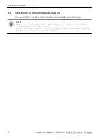
Страница 100: ...ain swit ched off for 3 5 s before you switch it on again If the device is switched on before 3 5 s have elapsed it must remain switched off for 5 minutes Switching the device on again to activate it is only possible after this time 4 4 Assembly and Commissioning 4 4 Switching The Device Off and On Again 42 Accessories Sync Transceiver Optical Electrical Converter for Time Synchronization Manual C...

Страница 101: ...e fiber optic connections using the covers provided for this purpose to protect them against the ingress of dust i i NOTE Do not use any liquids for cleaning 4 5 Assembly and Commissioning 4 5 Maintenance Accessories Sync Transceiver Optical Electrical Converter for Time Synchronization Manual 43 C53000 G9050 C168 1 Edition 09 2019 ...

Страница 102: ...s on human health and the environment i i NOTE Our products and batteries must not be disposed of as household waste For disposing batteries it is neces sary to observe the local national international directives Disposal of Mobile Storage Devices e g USB Sticks and Memory Cards When disposing of transferring mobile storage devices using the format or delete functions only changes the file managem...

Страница 103: ... 46 5 2 Interfaces 48 5 3 Environmental Conditions 49 5 4 Electrical Tests 50 5 5 Mechanical Tests 51 5 Accessories Sync Transceiver Optical Electrical Converter for Time Synchronization Manual 45 C53000 G9050 C168 1 Edition 09 2019 ...

Страница 104: ...solated 2 pole terminal Maximum contact voltage with a resistive load AC 240 V Maximum switching current 5 A Maximum switching power AC 2000 VA Permissible current for contacts 5 A Test voltage VRMS 3 51 kV Electronic Load Disconnecting Relay K2 Binary outputs OPTOMOS DC 24 VDC to 250 V 15 20 Permissible current for contacts 100 mA Minimum switching current 1 mA Maximum switching power Maximum 250...

Страница 105: ... X1 Cleared 15 ns falling edge at X1 Raising 30 ns rising edge at X1 Fuses Not replaceable T 2 0 A Replaceable T 1 6 A at AC 250 V or DC 300 V Safety As per DIN EN 61010 Part 1 overvoltage category III Degree of pollution 2 Fire resistance rating as per UL 94 V0 Technical Data 5 1 Device Data Accessories Sync Transceiver Optical Electrical Converter for Time Synchronization Manual 47 C53000 G9050 ...

Страница 106: ...output side Maximum output current Protocols IRIG B Pulses per second PPS DCF77 Minute pulse Minimum pulse length 2 ms Optical Interface R1 R2 Optical receivers 2 receivers factory setting light idle state OFF Fiber optic connection ST bayonet closure Data indication RCV1 LED yellow channel 1 receive Data indication RCV2 LED yellow channel 2 receive Wavelength 820 nm Sensitivity 30 dBm Optical bud...

Страница 107: ...imum relative humidity 95 on 30 days per year Condensation during operation Not permitted Condensation during transport and storage Permitted Maximum altitude above sea level 2000 m Degree of pollution 2 Protection class as per IEC 60529 IP 20 Overvoltage category III 5 3 Technical Data 5 3 Environmental Conditions Accessories Sync Transceiver Optical Electrical Converter for Time Synchronization ...

Страница 108: ...3 Class III 2 5 kV direct axis voltage component 1 kV differen tial mode voltage Electrostatic discharge test IEC 60255 26 Class III EN 61000 4 2 Class III 6 kV contact discharge 8 kV air discharge both polarities 150 pF Ri 330 Ω Radiated HF field interference amplitude modulated IEC 61000 4 3 10 V m 80 MHz to 1000 MHz 80 AM 1 kHz Radiated HF field interference pulse modulated IEC 61000 4 3 35 V m...

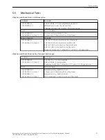
Страница 109: ... 8 Hz to 35 Hz 1 g acceleration vertical axis Frequency sweep rate 1 octave min 1 cycle in 3 orthogonal axes Vibration and Shock Stress during Transport and Storage Oscillation Sinusoidal IEC 60068 2 6 IEC 60255 21 1 Class 2 5 Hz to 8 Hz 7 5 mm amplitude 8 Hz to 150 Hz 2 g acceleration Frequency sweep rate 1 octave min 20 cycles in 3 orthogonal axes Shock Semi sinusoidal IEC 60068 2 27 IEC 60255 2...

Страница 110: ...52 Accessories Sync Transceiver Optical Electrical Converter for Time Synchronization Manual C53000 G9050 C168 1 Edition 09 2019 ...

Страница 111: ...Appendix A 1 Ordering Information 54 A 2 Dimensions 55 A Accessories Sync Transceiver Optical Electrical Converter for Time Synchronization Manual 53 C53000 G9050 C168 1 Edition 09 2019 ...

Страница 112: ... pulse for the 7SD52 or minute pulse for SIPROTEC devices Fiber optic connection to 62 5 µm 125 µm Multimode optical fiber via ST connector to GPS time synchronization unit 7XV5664 1AA00 Electrical connection to the SIPROTEC devices using the Y bus cable 7XV5104 or 7XV5105 7SD52 only For DIN rail mounting A 1 Appendix A 1 Ordering Information 54 Accessories Sync Transceiver Optical Electrical Conv...

Страница 113: ...iver_7XV5654_big 1 en_US Figure A 1 Dimensions in mm Values in Brackets in inches A 2 Appendix A 2 Dimensions Accessories Sync Transceiver Optical Electrical Converter for Time Synchronization Manual 55 C53000 G9050 C168 1 Edition 09 2019 ...

Страница 114: ...56 Accessories Sync Transceiver Optical Electrical Converter for Time Synchronization Manual C53000 G9050 C168 1 Edition 09 2019 ...

Отзывы: