7SR210 & 7SR220 Configuration Guide
List of Figures
Figure 1.1-1 Menu…………………………………………………………………………………………...........................4
Figure 1.1-2 Fascia Contrast Symbol…………………………………………………………….……… .........................4
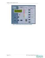
Figure 1.1-3 Relay Fascia…………………………………………………………….………...........................................5
Figure 1.2-1 Relay Identifier Screen…………………………………………………..………….……......................... …6
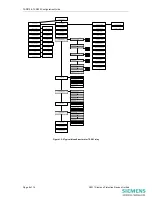
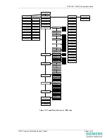
Figure 1.2-3 Menu Structure for 7SR21 relay……………………………………..…………….…… ......................... …7
Figure 1.2-4 Menu Structure for 7SR22 relay……………………………………………………...…......................... …8
Figure 2.1-1 USB connection to a PC……………………………………………….……………….… ..................... …11
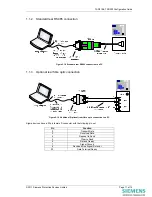
Figure 2.1-2 Standard rear RS485 connection to a PC………………………………………….…………………. .. …12
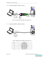
Figure 2.1-3 Additional (Optional) rear fibre optic connection to a PC………………………………………….… .. …12
Figure 2.1-4 Additional (Optional) rear RS485 + IRIG-B connection to a PC………………….…………………. . …13
Figure 2.1-5 Additional (Optional) rear RS232 + IRIG-B connection to a PC…………………………………….……13
Figure 2.1-6 PC Comm Port Selection…………………………………………………………….…......................... …14
Page 4 of 14
©2011 Siemens Protection Devices Limited

