background image

7SR10, 7SR11, 7SR12 Applications Guide


© 2018 Siemens Protection Devices Limited 


Chapter 7 Page 16 of 41 


V

Transformer Feeders

(Cable Circuits)

- 45

0

MTA

Current lagging 

Voltage

   Plain Feeders

(Overhead Lines)

- 30

0

MTA

I

V

I


Figure 2-9     Phase Fault Angles 

 
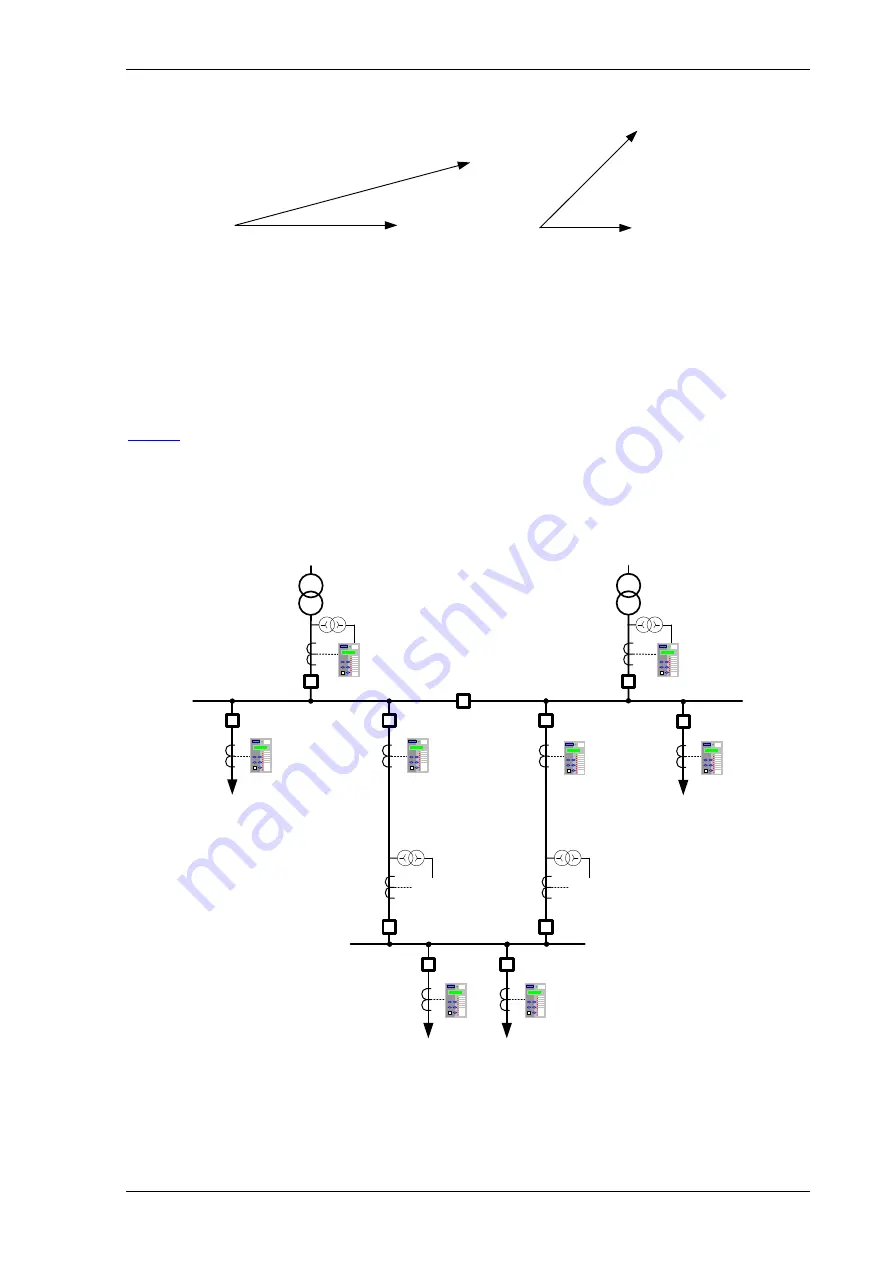
Directional overcurrent elements allow greater fault selectivity than non-directional elements for interconnected 

systems where fault current can flow in both directions through the relaying point. Consider the network shown in 

Fig. 2.10

The Circuit breakers at A, B, E and G have directional overcurrent relays fitted since fault current can flow in both 

directions at these points. The forward direction is defined as being away from the busbar and against the 

direction of normal load current flow. These forward looking IDMTL elements can have sensitive settings applied 

i.e. low current and time multiplier settings. Note that Directional overcurrent  relays may be programmed with 

forward, reverse and non-directional elements simultaneously when required by the protection scheme. 
 

Load

A

C

E

B

D

G


Figure 2-10    Application of Directional Overcurrent Protection 


Содержание 7SR10 Argus Series

Страница 1: ...7SR10 Argus Overcurrent Relay Reyrolle Protection Devices ...

Страница 2: ...Siemens Protection Devices Limited 2 ...

Страница 3: ... model or article be reproduced from this document unless Siemens Protection Devices Limited consent While the information and guidance given in this document is believed to be correct no liability shall be accepted for any loss or damage caused by any error or omission whether such error or omission is the result of negligence or any other cause Any and all such liability is disclaimed 2018 Sieme...

Страница 4: ...imed 2018 Siemens Protection Devices Limited 7SR10 Description of Operation Document Release History This document is issue 2018 07 The list of revisions up to and including this issue is 2018 07 Twelfth Issue 2018 06 Eleventh Issue 2017 09 Tenth Issue 2017 07 Nineth Issue 2017 04 Eighth Issue 2017 03 Seventh Issue 2016 11 Sixth Issue 2015 09 Fifth Issue 2015 06 Fourth Issue 2015 03 Third Issue 20...

Страница 5: ...nt Protection 51 27 3 1 4 Current Protection Voltage Controlled Overcurrent 51V 29 3 2 Current Protection Derived Earth Fault 67N 51N 50N 30 3 2 1 Directional Control of Derived Earth Fault Protection 67N 30 3 2 2 Instantaneous Derived Earth Fault Protection 50N 31 3 2 3 Time Delayed Derived Earth Fault Protection 51N 32 3 3 Current Protection Measured Earth Fault 67G 51G 50G 34 3 3 1 Directional ...

Страница 6: ...aint 81HBL2 Phase Elements Only 63 5 3 Total Harmonic Distortion Supervision 81THD 63 5 4 VT Supervision 60VTS 64 5 5 CT Supervision 60CTS 65 5 5 1 60CTS I 65 5 5 2 60CTS 66 5 6 Broken Conductor 46BC 66 5 7 Trip Close Circuit Supervision 74TCS 74CCS 67 Section 6 Other Features 68 6 1 Data Communications 68 6 1 1 Communication Ports 68 6 2 CB Maintenance 71 6 2 1 Output Matrix Test 71 6 2 2 CB Coun...

Страница 7: ...gure 3 13 Logic Diagram 7SR10 SEF Instantaneous Element 38 Figure 3 14 Logic Diagram 7SR10 SEF Time Delayed Element 51SEF 39 Figure 3 15 Logic Diagram 7SR10 SEF Time Delayed Element 51SEF 39 Figure 3 16 Logic Diagram High Impedance REF 64H 40 Figure 3 17 Logic Diagram Cold Load Settings 51c 41 Figure 3 18 Logic Diagram Negative Phase Sequence Overcurrent 46NPS 42 Figure 3 19 Logic Diagram Phase Cu...

Страница 8: ...am Trip Circuit Supervision Feature 74TCS 67 Figure 5 9 Logic Diagram Close Circuit Supervision Feature 74CCS 67 Figure 6 1 Communication to Front USB Port 68 Figure 6 2 Connect Icon 68 Figure 6 3 Port Selection in Connection Manager 69 Figure 6 4 System Information Icon 69 Figure 6 5 System Information Icon 70 Figure 6 6 Communication to Multiple Devices from Control System using RS485 71 Figure ...

Страница 9: ...R10 Description of Operation 2018 Siemens Protection Devices Limited Chapter 1 Page 6 of 77 List of Tables Table 2 1 Summary of 7SR10 Argus Overcurrent Relay Configurations 14 Table 6 1 Operation Mode 75 ...

Страница 10: ...imited Chapter 1 Page 7 of 77 Symbols and Nomenclature The following notational and formatting conventions are used within the remainder of this document Setting Menu Location MAIN MENU SUB MENU Setting Elem name Setting Setting value value Alternatives 1st 2nd 3rd ...

Страница 11: ... using the latest generation of hardware technology and is available in multiple variants depending on power supply binary input output configuration voltage input and data communication facility 7SR10 is a member of Siemens Reyrolle protection devices Argus product family The 7SR10 overcurrent relay consists of non directional functions and with additional voltage inputs providing directional fun...

Страница 12: ... Standard Version with Breaker Control Push Buttons 2 Protection Function Packages C Standard version included in all models 46BC Broken conductor Load unbalance 46NPS Negative phase sequence overcurrent 49 Thermal overload 50 Instantaneous phase fault overcurrent 50BF Circuit breaker fail 50G N Instantaneous earth fault 50SEF 2 4 Instantaneous sensitive earth fault overcurrent 51 Timed delayed ph...

Страница 13: ...rvoltage 32 Power 32S Sensitive Power 37 Undercurrent 37G 1 Undercurrent measured earth fault 37SEF 2 Undercurrent sensitive earth fault 46BC Broken conductor Load Unbalance 46NPS Negative phase sequence overcurrent 47NPS Negative phase sequence overvoltage 49 Thermal overload 50BF Circuit breaker fail 51V Voltage dependent overcurrent 55 Power Factor 59N Neutral voltage displacement 60CTS CT supe...

Страница 14: ...ptional Version D software Fig 1 7SR10 Overcurrent Relay Non Directional 7SR10 64H 46 BC 46 NPS x2 37 x2 49 50 BF V1 V2 V3 37 x2 49 50 BF 37 x2 49 50 BF 60 CTS 74 T CCS 67 50 x4 67 51 x4 67 50N x4 67 50 x4 67 50 x4 67 51 x4 67 51 x4 67 51N x4 67 50G x4 67 51G x4 27 59 x4 27 59 x4 27 59 x4 59N x2 47 x2 50 BF 50 BF 37 SEF x2 81 HBL2 81 HBL2 81 HBL2 51V 51V 51V 67 50SEF x4 67 51SEF x4 81 x4 86 IL1 IA...

Страница 15: ...table for ring type lug connection to provide a secure and reliable termination 1 6 1 Terminal Diagram with Control Push Buttons BI1 Term RS485 A GND B ve ve 1 2 3 1 2 BI2 ve ve 3 4 BI3 ve ve 5 6 1 2 3 4 BI4 ve ve 7 8 BI5 ve ve 9 10 BI6 ve ve 11 12 X2 X3 X4 X5 BO3 7 8 BO5 11 12 BO6 13 14 IL4 5A 10 11 12 1A IL3 5A 7 8 9 1A IL2 5A 4 5 6 1A IL1 5A 1 2 3 1A 5 6 4 BO2 BO1 2 3 1 BO4 9 10 X1 GND L N E Fi...

Страница 16: ... ve ve 11 12 X2 X3 X4 X5 BO3 7 8 BO5 11 12 BO6 13 14 IL4 5A 10 11 12 1A IL3 5A 7 8 9 1A IL2 5A 4 5 6 1A IL1 5A 1 2 3 1A 5 6 4 BO2 BO1 2 3 1 BO4 9 10 X1 BI7 ve ve 1 2 BI8 ve ve 3 4 BI9 ve ve 5 6 X6 V1 1 2 V2 3 4 V3 5 6 X7 GND L N E Fig 4 Terminal Wiring Diagram of 7SR10 Directional Overcurrent Relay NOTE For DC variants connect the positive and negative terminals to X3 L and X3 N terminals respecti...

Страница 17: ... 7SR10 Argus Overcurrent Relay is assembled from the following modules 1 Front Fascia with 9 configurable LEDs and 1 Relay Healthy LED 2 Processor module 3 Current Analogue Voltage Analogue Input module and Output module With control push buttons 4 x Current Terminal X5 6 x Binary Input Terminal X1 6 x Binary Outputs Terminal X4 3 x Voltage Inputs Terminal X7 3 x Binary Input Terminal X6 4 Communi...

Страница 18: ...us Overcurrent Relay with Control Push Buttons 2 3 CB Open Close The circuit breaker CB control function is used to manually open and close the CB when it is connected to the network Two dedicated push buttons are provided on the HMI to execute the CB manual close and open operations Button Function Description Close Press Close button and confirm ENTER to execute the close operation of circuit br...

Страница 19: ...ay is supplied with the following nominal power supply ranges 60 V 240 V AC DC power supply BI threshold 88 V AC DC or 44 V AC DC 24 V 60 V DC power supply BI threshold 19 V DC The power supply module is equipped with 3 or 6 Binary Inputs It also consists of one RS485 communication interface half duplex for communicating with RTUs and parameterization of relays via remote locations For AC connecti...

Страница 20: ...itably 2 5 1 Connectors with Control Push Buttons Current Inputs Binary Output Binary Input Rear Communication Port Auxiliary Supply Current Inputs Binary Output Auxiliary Supply Rear Communication Port Voltage Inputs Binary Input Figure 2 2 7SR10 Non Directional and Directional Overcurrent Relay with Connectors 2 6 Relay Information The rating label is located on the housing and provides more tec...

Страница 21: ...stand 5kV WEEE Symbol instructions The product should not be disposed with other wastes at the end of its working life Please separate the product from other types of wastes and recycle it responsibly to promote the sustainable reuse of material resources This will help prevent harm to the environment or human health from uncontrolled waste disposal For safety reasons the following symbols are dis...

Страница 22: ...be programmed each triggered from one or more input Each general alarm will also generate an event If multiple alarms are activated simultaneously the messages are displayed on a separate page in a rolling display on the LCD The System Config General Alarm Alert setting Enabled Disabled allows the user to select if the alarms are to be displayed on the LCD when active All general alarms are raised...

Страница 23: ...e front fascia A template is available in the Reydisp software tool to allow users to create and print customised legends Each LED can be programmed as hand reset or self reset Hand reset LEDs can be reset either by pressing the TEST RESET button energising a suitably programmed binary input or by sending an appropriate command over the data communications channel s The status of hand reset LEDs i...

Страница 24: ...relay to provide panel indications and alarms Each binary input is set by default to be read when the relay is in both the local or remote condition A setting is provided to allow the user to select if each individual input shall be read when the relay is in the local or remote condition in the INPUT CONFIG BINARY INPUT CONFIG menu Event BI 1 Binary Input 1 1 Inverted Inputs BI 1 inverted BI 1 P U...

Страница 25: ...ver the data communications channel s On loss of the auxiliary supply hand reset outputs will reset When the auxiliary supply is re established the binary output will remain in the reset state unless the initiating condition is still present Notes on General Pickup An output General Pickup is available to indicate that the pickup level has been exceeded for one or more protection functions Any pro...

Страница 26: ...is is done in the MAINTENANCE MENU START COUNT menu using the Start Types setting All the start up types selected ticked will be added to the overall start up count The number of restarts before the alarm output is raised is set in the MAINTENANCE MENU START COUNT menu using the Start Count Target setting When the number of relay start ups reaches the target value an output is raised OUTPUT MATRIX...

Страница 27: ... on A changeover or open contact can be mapped via the binary output matrix to provide an external protection healthy signal A changeover or closed contact can be mapped via the binary output matrix to provide an external protection defective signal With the Protection Healthy this contact is open When the auxiliary supply is not applied to the relay or a problem is detected within the relay then ...

Страница 28: ...hieved for the phase fault elements using the quadrature voltage i e at unity power factor I leads V by 90 Each phase current is compared to the voltage between the other two phases i e for normal phase sequence 1 2 3 IL1 V23 IL2 V31 IL3 V12 When the device is applied to reverse sequence networks i e 1 3 2 the polarizing is corrected internally by the Gn Phase Rotation setting in the CT VT Config ...

Страница 29: ...eous element 50 n has independent settings 50 n Setting for pick up current and 50 n Delay follower time delay The instantaneous elements have transient free operation Where directional elements are present the direction of operation can be set using 50 n Dir Control setting Directional logic is provided independently for each 50 n element e g giving the option of using two elements set to forward...

Страница 30: ... A number of shaped characteristics are provided An inverse definite minimum time IDMT characteristic is selected from IEC ANSI or user specific curves using 51 n Char A time multiplier is applied to the characteristic curves using the 51 n Time Mult setting Alternatively a definite time lag delay DTL can be chosen using 51 n Char When Definite Time Lag DTL is selected the time multiplier is not a...

Страница 31: ... Charact 51 n Time Mult 51 n Delay DTL 51 n Reset c Forward Reverse 51 n Dir Control Non Dir 1 1 1 51 n Follower DTL L1 Dir En L2 Dir En L3 Dir En L1 Dir En L2 Dir En L3 Dir En IL1 Fwd IL1 Rev IL2 Fwd IL2 Rev IL3 Fwd IL3 Rev 1 1 1 Non Dir 51 n VTS Action Off Inhibit VT Fail 51 n Min Operate Time IL1 IL2 IL3 50 51 Measurement See Voltage Controlled Overcurrent 51V L1 81HBL2 51c 51 n Inrush Action O...

Страница 32: ...n pickup current setting 51 n Multiplier is applied to each phase independently when its control phase phase voltage falls below VCO Setting The voltage levels used for each phase over current element are shown in the table below Relays with a Ph N connection automatically calculate the correct Ph Ph control voltage Current Element Control Voltage IL1 V12 IL2 V23 IL3 V31 The Voltage Controlled Ove...

Страница 33: ... zero sequence path or an open delta VT connection the earth fault element can use zero sequence voltage and current for polarisation If zero sequence polarising voltage is not available e g when a two phase phase to phase connected VT is installed then negative sequence voltage and negative sequence currents must be used The type of VT connection is specified by Voltage Config CT VT CONFIG menu S...

Страница 34: ...ments set to forward and two to reverse Operation of the instantaneous earth fault elements can be inhibited from Inhibit 50N n A binary or virtual input 79 E F Inst Trips 50N n When delayed trips only are allowed in the auto reclose sequence 79 E F Prot n Trip n Delayed 50N n Inrush Action Block Operation of the inrush current detector function 50N n VTSAction Inhibit Operation of the VT Supervis...

Страница 35: ...on is configured as an IEC or ANSI or user characteristic if the reset is selected as IEC ANSI DECAYING reset the associated reset curve will be used The reset mode is significant where the characteristic has reset before issuing a trip output see Applications Guide A minimum operate time for the characteristic can be set using the 51N n Min Operate Time setting A fixed additional operate time can...

Страница 36: ...d and the 51N n Dir En signal is set TRUE Forward Reverse 51N n Dir Control Non Dir 1 51N n Dir En 67N Fwd 67N Rev 51N n VTS Action Off Non Dir Inhibit VT Fail 1 IL1 IL2 IL3 IN 51N n Delay DTL 51N n Follower DTL c Pickup trip Inhibit 50N n 51N n Element Enabled Disabled 81HBL2 51N n Inrush Action Off Inhibit 51N n Dir En 79 P F Inst Trips 51N n 79 P F Prot n Trip n Delayed AUTORECLOSE Figure 3 7 L...

Страница 37: ...tage must be adjusted such that the directional detector gives maximum sensitivity in the forward operate zone when the current is in phase with it The reverse operate zone is the mirror image of the forward zone The measured directional earth fault elements use zero phase sequence ZPS polarising Voltage polarisation is achieved for the earth fault elements by comparison of the appropriate current...

Страница 38: ... g giving the option of using two elements set to forward and two to reverse Operation of the instantaneous measured earth fault elements can be inhibited from Inhibit 50G n A binary or virtual input 79 E F Inst Trips 50G n When delayed trips only are allowed in the auto reclose sequence 79 E F Prot n Trip n Delayed 50G n Inrush Action Block Operation of the inrush current detector function 50G n ...

Страница 39: ...erate time for the characteristic can be set using 51G n Min Operate Time setting A fixed additional operate time can be added to the characteristic using 51G n Follower DTL setting Where directional elements are present the direction of operation can be set using 51G n Dir Control setting Directional logic is provided independently for each 51G n element e g giving the option of using two element...

Страница 40: ...rd directional zone is symmetrical around the characteristic angle with angular limits defined in the performance specification The reverse operate zone is the mirror image of the forward zone The directional sensitive earth fault elements use zero phase sequence ZPS polarising Voltage polarisation is achieved for the earth fault elements by comparison of the appropriate current with its equivalen...

Страница 41: ...the zero sequence voltage V0 is above the 67SEF Minimum Voltage setting i e the residual voltage is greater than 3 times this setting and the phase is in the Forward Reverse operating range 50SEF n c 50SEF n Setting 50SEF n Delay I4 ISEF General Pickup Inhibit 50SEF n 50SEF n Element Enabled Disabled 79 P F Inst Trips 50SEF n 79 P F Prot n Trip n Delayed AUTORECLOSE Figure 3 12 Logic Diagram 7SR10...

Страница 42: ...h fault elements can be inhibited from Inhibit 51SEF n A binary or virtual input 79 SEF Inst Trips 51SEF n When delayed trips only are allowed in the auto reclose sequence 79 SEF Prot n Trip n Delayed 51SEF n VTSAction Inhibit Operation of the VT Supervision function Directional elements will not operate unless the zero sequence voltage V0 is above the 67SEF Minimum Voltage setting i e the residua...

Страница 43: ... n can be applied for a period following circuit switch in The Cold Load settings are applied after the circuit breaker has been open for longer than the Pick Up Time setting Following circuit breaker closure the cold load overcurrent settings will revert to those defined in the Phase Overcurrent menu 51 n after either elapse of the Drop Off Time setting or when the measured current falls below th...

Страница 44: ...equence is corrected automatically by the Gn Phase Rotation setting in the CT VT Config menu Two NPS current elements are provided 46IT and 46DT The 46IT element can be configured to be either definite time lag DTL or inverse definite minimum time IDMT 46IT Setting sets the pick up current level for the element A number of shaped characteristics are provided An inverse definite minimum time IDMT c...

Страница 45: ... and two for the earth or sensitive earth fault input 37G 1 37G 2 or 37SEF 1 37SEF 2 Each phase has an independent level detector and current timing element 37 n Setting sets the pick up current An output is given after elapse of the 37 n Delay setting An output is also given to indicate the operated phase All under current elements work with True RMS currents Operation of the under current elemen...

Страница 46: ...the current rise above the 49 Overload Setting for a defined time an output signal will be initiated The operating time is a function of thermal time constant 49 Time Constant and previous current levels Operate Time t 2 B 2 2 P 2 I k I I I ln t τ Where T Time in minutes τ 49 Time Constant setting minutes In Log Natural I measured current IP Previous steady state current level k Constant recommend...

Страница 47: ...Voltage 27 59 In total four under over voltage elements are provided 27 59 1 27 59 2 27 59 3 27 59 4 The relay utilises fundamental frequency RMS voltage for this function All under over voltage elements have a common setting to measure phase to phase Ph Ph or phase to neutral Ph N voltage using the Voltage Input Mode setting Voltage elements can be blocked if all phase voltages fall below the 27 ...

Страница 48: ...nced voltage in the system The relay derives the NPS voltage from the three input voltages VL1 VL2 and VL3 Two elements are provided 47 1 47 2 Voltage elements can be blocked if all phase voltages fall below the 47 U V Guard setting 47 n Setting sets the pick up voltage level for the element The 47 n Hysteresis setting allows the user to vary the pick up drop off ratio for the element An output is...

Страница 49: ...hosen using 59NITChar When Delay DTL is selected the time multiplier is not applied and the 59NIT Delay DTL setting is used instead An instantaneous or definite time delayed reset can be applied using the 59NIT Reset setting The 59NDT element has a DTL characteristic 59NDT Setting sets the pick up voltage 3V0 and 59NDT Delay the follower time delay Operation of the neutral overvoltage elements can...

Страница 50: ...blocked if all phase voltages fall below the 81 U V Guard setting The sense of the element under frequency or over frequency is set by the 81 n Operation setting 81 n Setting sets the pick up voltage level for the element An output is given after elapse of the 81 n Delay setting The 81 n Hysteresis setting allows the user to vary the pick up drop off ratio for the element Operation of the under ov...

Страница 51: ... level or on the total power of all three phases An output is given after elapse of the Gn 32 n Delay setting Operation of the under over power elements can be inhibited when The measured current is below the Gn 32 n U C Guard setting A VT Fail condition is detected Inhibit 32 n A binary or virtual input V1 IL1 V2 V3 IL3 IL2 Enabled Enabled En Inhibit VT Fail W VAr W VAr W VAr W VAr Gn32 n Operati...

Страница 52: ...easured Gn 32S n Setting sets the pick up power level for the element Under power or over power operation can be set by the Gn 32S n Operation setting An output is given after elapse of the Gn 32S n Delay setting Operation of the under over power elements can be inhibited when The measured current is below the Gn 32S U C Guard setting A VT Fail condition is detected Inhibit 32S n A binary or virtu...

Страница 53: ... power factor of all three phases An output is given after elapse of the Gn 55 n Delay setting Operation of the power factor elements can be inhibited when The measured current is below the Gn 55 U C Guard setting A VT Fail condition is detected Inhibit 55 n A binary or virtual input V1 IL1 V2 V3 IL3 IL2 Enabled Enabled En Inhibit VT Fail W VAr W VAr W VAr W VAr Gn55 n Operation Under Over Gn 55 n...

Страница 54: ...nctionality CB auxiliary switches must be connected to CB Closed and CB Open binary inputs A circuit breaker s service status is determined by its position i e from the binary inputs programmed CB Open and CB Closed The circuit breaker is defined as being in service when it is closed The circuit memory functionality prevents autoreclosing when the line is de energised or normally open AR is starte...

Страница 55: ...p 79 Ext Pickup 79 Block Reclose Block Close CB Close CB Open CB 79 Trip Reclose 79 Trip Lockout 79 Line Check 79 Reset Lockout 79 Lockout Hot Line In Hot Line Out Outputs Outputs are fully programmable to either binary outputs or LEDs Programmable outputs include 79 Out Of Service 79 In Service 79 In Progress 79 AR Close CB Manual Close CB 79 Successful AR 79 Lockout 79 Close Onto Fault 79 Trip R...

Страница 56: ...shot count advances automatically applies the correct type of Protection and associated Dead time for that fault type at that point in the sequence A typical sequence would consist of two Inst trips followed by at least one Delayed trip This sequence enables transient faults to be cleared quickly by the Inst trip s and permanent fault to be cleared by the combined Delayed trip The delayed trip mus...

Страница 57: ...time Reclose Block is allowed to be raised if this time delay expires the Relay will go to Lockout If Reclose Block is cleared before this time expires then the CB Close pulse will be issued at that point in time Dead Time Reclose Blocked Delay Lockout 79 Sequence Fail Timer Sets the time that AutoReclose start can be primed Where this time expires before all the DAR start signals are not received...

Страница 58: ...ayed 79 P F Deadtime 3 Sets the third Reclose Delay Dead time in the P F sequence 79 P F Prot n Trip 4 The fourth protection Trip in the P F sequence can be set to either Inst or Delayed 79 P F Deadtime 4 Sets the fourth Reclose Delay Dead time in the P F sequence 79 P F Prot n Trip5 The fifth and last protection Trip in the P F sequence can be set to either Inst or Delayed 79 P F HighSet Trips to...

Страница 59: ...P F Prot n Trip5 Not Blocked Blocked Blocked raises an output which can be mapped to a Binary output to Block an External Protection s fifth Trip Output 79 P F Extern Trips to Lockout Sets the number of allowed External protection trips Relay will go to Lockout on the last Trip These settings allow the user to set up a separate AutoReclose sequence for external protection s having a different sequ...

Страница 60: ...ts 79 Retry Interval Close CB Pulse Block Close CB Reclaim Timer 79 Successful AR 79 Block Reclose AND 79 Reclose Blocked Delay Elapsed Starter raised in Reclaim Time Reclaim Time Elapsed Lockout Reset Sequence Fail Timer Elapsed Increment Close Count Close Pulse Expired Close CB AR Started CB Closed 79 Elem Prot Trip n LOCKOUT RESET 79 Minimum LO Delay 79 Reset LO by Timer Manual Close CB Closed ...

Страница 61: ...e of Nomenclature E1 I1 F1 O2 L1 Equation 1 Binary Input 1 XOR Function Key 1 AND NOT Binary Output 2 OR LED 1 When the equation is satisfied 1 it is routed through a pick up timer En Pickup Delay a drop off timer En Dropoff Delay and a counter which instantaneously picks up and increments towards its target En Counter Target P U D E L A Y D O D E L A Y T Counter Value 1 2 Increment Counter Equati...

Страница 62: ...rops off This can lead to multiple control restarts due to bounce on the binary input signal With Latch operation the close or trip sequence always continues to completion or sequence failure and bounce on the binary input is ignored Reset operation can be useful however as it allows a close or trip sequence to be aborted by dropping off the binary input signal Close CB Delay The Close CB Delay is...

Страница 63: ...pen at the end of the reclaim time or a protection operates during the final reclaim time CB Control Trip Time When this is set to Enabled the relay will measure the CB trip time following operation of either a CB control open output or a CB Trip output The trip time is displayed by the MAINTENANCE METERS CB Trip Time meter When this is set to Disabled the relay will measure the trip time followin...

Страница 64: ...out Delay timer can be set to delay a too fast manual close after lockout this prevents an operator from manually closing onto the same fault too quickly and thus performing multiple sequences and possibly burning out Plant 79 Reset LO by Timer Only in Auto reclose models Set to Enabled this ensures that the Lockout condition is reset when the timer expires Lockout indication will be cleared other...

Страница 65: ...B fail outputs will be issued by providing any of the 3 phase currents are above the 50BF Setting or the current in the fourth CT is above 50BF I4 for longer than the 50BF n Delay setting or for a mechanical protection trip the circuit breaker is still closed when the 50BF n Delay setting has expired indicating that the fault has not been cleared Both 50BF 1 and 50BF 2 can be mapped to any output ...

Страница 66: ...ured value of the second harmonic component is above the 81HBL2 setting NOTE The output should be configured as either Pulse output or Hand reset output only 81HBL2 Element Enabled Disabled IL1 IL2 IL3 81HBL2 Bias L2 81HBL2 81HBL2 Setting c L1 81HBL2 L3 81HBL2 81HBL2 1 Inhibit 81HBL2 Figure 5 2 Logic Diagram Harmonic Block Feature 81HBL2 5 3 Total Harmonic Distortion Supervision 81THD Single stage...

Страница 67: ...VT is considered to have failed where the voltage exceeds 60VTS V while the current is below 60VTS I for a time greater than 60VTS Delay 3 Phase Failure Detection Under normal load conditions rated PPS voltage would be expected along with a PPS load current within the circuit rating Where PPS load current is detected without corresponding PPS voltage this could indicate a three phase VT failure To...

Страница 68: ... CT Supervision 60CTS The relay has two methods of detecting a CT failure CT Supervision is only available in relays with four current inputs and three voltage inputs 5 5 1 60CTS I The current from each of the Phase Current Transformers is monitored If one or two of the three input currents falls below the CT supervision current setting CTS I for more than 60CTS Delay then a CT failure output 60CT...

Страница 69: ... If the negative sequence current exceeds its setting while the negative sequence voltage is below its setting for more than 60CTS Delay then a CT failure output 60CTS Operated is given Operation of the CT supervision elements can be inhibited from Inhibit 60CTS A binary or virtual input 60CTS Delay VL1 VL2 VL3 NPS Filter V2 60CTS Vnps IL1 IL2 IL3 NPS Filter I2 60CTS Inps Inhibit 60CTS 60CTS Eleme...

Страница 70: ...he trip circuit wiring is intact If all mapped inputs become de energised due to a break in the trip circuit wiring or loss of supply an output is given The 74TCS n Delay setting prevents failure being incorrectly indicated during circuit breaker operation This delay should be greater than the operating time of the circuit breaker The use of one or two binary inputs mapped to the same Trip Circuit...

Страница 71: ... port is connected using a standard USB cable with a type B connection to the relay and type A to the PC The PC will require a suitable USB driver to be installed this will be carried out automatically when the Reydisp software is installed When the Reydisp software is running with the USB cable connected to a device an additional connection is shown in the Reydisp connection window connections to...

Страница 72: ...ces Limited Chapter 1 Page 69 of 77 2 Select COM port where the 7SR10 relay is connected Figure 6 3 Port Selection in Connection Manager 3 Select System Information icon Figure 6 4 System Information Icon 4 Confirm the connection establishment with the Reydisp ...

Страница 73: ...ays are fitted with an internal terminating resistor which can be connected between A and B by fitting an external wire loop between terminals X2 TERM and X2 B terminals The maximum number of relays that can be connected to the bus is 64 The following settings must be configured via the relay fascia when using the RS485 interface The shaded settings are only visible when DNP3 0 is selected Setting...

Страница 74: ...ix Test The feature is only visible from the Relay fascia and allows the user to operate the relays functions The test of the function will automatically operate any Binary Inputs or LED s already assigned to that function Any protection function which is enabled in the setting menu will appear in the Output Matrix Test 6 2 2 CB Counters The following CB maintenance counters are provided CB Total ...

Страница 75: ...torage menu contains the settings for the Demand Waveform and Fault storage features NOTE ZY20 The user selectable language parameter will be available in Turkish while the default data like events and waveform recorder will be available in English 6 3 2 Demand Maximum minimum and mean values of line currents voltages and power where applicable are available as instruments which can be read in the...

Страница 76: ... can select the percentage of the waveform storage prior to triggering Waveforms are sampled at a rate of 1600 Hz Stored waveforms can be erased using the DATA STORAGE Clear Waveforms setting or from Reydisp 6 3 5 Fault Records Up to fifteen fault records can be stored and displayed on the Fascia LCD Fault records can be triggered by user selected via relay operations or via a suitably programmed ...

Страница 77: ...truments and communications protocols The value is stored in the range 0 999999 which continues from zero automatically when 999999 is reached 6 3 7 Disk Activity Warning The Data Storage facilities offered by the Relay involve archiving a huge amount of data to non volatile memory Since such functionality is always secondary to the Protection functionality offered by the Relay this means that dat...

Страница 78: ... Option Setting Option Disabled Binary Outputs Enabled Enabled Disabled Reporting Spontaneous IEC Enabled Enabled Disabled DNP Enabled Enabled Disabled General Interrogation IEC Enabled Enabled Disabled DNP Enabled Enabled Disabled MODBUS Enabled Enabled Enabled Changing of Settings Rear Ports Enabled Disabled Enabled Fascia Enabled Enabled Enabled USB Disabled Enabled Enabled Historical Informati...

Страница 79: ...roup of settings can be active SYSTEM CONFIG Active Group setting It is possible to edit one group while the relay operates in accordance with settings from another active group using the View Edit Group setting Some settings are independent of the active group setting i e they apply to all settings groups This is indicated on the top line of the relay LCD where only the Active Group No is identif...

Страница 80: ... s The Control Password prevents unauthorised operation of controls in the relay Control Menu from the front fascia The password validation screen also displays a numerical code If the password is lost or forgotten this code should be communicated to Siemens Limited and the password can be retrieved NOTE The default control password is AAAA It is recommended to change the default password after th...

Страница 81: ...nt Release History This document is issue 2018 06 The list of revisions up to and including this issue is 2018 06 Eleventh Issue 2017 09 Tenth Issue 2017 07 Nineth Issue 2017 04 Eighth Issue 2017 03 Seventh Issue 2016 11 Sixth Issue 2015 09 Fifth Issue 2015 06 Fourth Issue 2015 03 Third Issue 2015 02 Second Issue 2013 11 First Issue ...

Страница 82: ...peration 5 1 3 Setting Mode 7 1 4 Instruments Mode 7 1 5 Fault Data Mode 14 Section 2 Setting Configuring the Relay Using Reydisp Evolution 15 2 1 Physical Connection 15 2 1 1 Front USB connection 15 2 1 2 Rear RS485 connection 15 2 1 3 Configuring Relay Serial Data Communication 16 2 1 4 Connecting to the Relay for setting via Reydisp 17 2 1 5 Configuring the user texts using Reydisp Language Edi...

Страница 83: ...8 List of Figures Figure 1 1 Menu 4 Figure 1 2 Fascia of a 7SR10 Relay Size 4 Case 4 Figure 1 3 Relay Identifier Screen 5 Figure 1 4 Menu Structure 6 Figure 2 1 USB connection to PC 15 Figure 2 2 RS485 connection to PC 15 Figure 2 3 PC Comm Port Selection 17 Figure 2 4 PC Language File Editor 18 ...

Страница 84: ...relay has detected Control Mode allows the user to control external plant under the relays control for example the CB All menus may be viewed without entering a password but actions will not be permitted if the relevant passwords have been set The menus can be viewed via the LCD by pressing the access keys as below Relay Identifier Setting Mode Instruments Fault Data Control Figure 1 1 Menu Pressi...

Страница 85: ...play the relays instrumentation and Fault data and to reset the output relays and LED s The five push buttons have the following functions READ DOWN READ UP Used to navigate the menu structure ENTER The ENTER push button is used to initiate and accept setting changes When a setting is displayed pressing the ENTER key will enter the edit mode the setting will flash and can now be changed using the ...

Страница 86: ...D CONFIG PICK UP CONFIG CB COUNTERS I2 T CB WEAR CONTROL MODE CB TRAVELLING CLOSE I OPEN AR OUT OF SERVICE AR TRIP RECLOSE AR TRIP LOCKOUT SEF IN HOTLINE WORKING OUT INST PROT N IN IN I OUT CONFIRM ACTION CONFIRM ACTION IN I OUT IN I OUT IN I OUT FAVOURITE METERS CURRENT METERS VOLTAGE METERS DIRECTIONAL METERS POWER METERS ENERGY METERS THERMAL METERS AUTORECLOSE METERS MAINTENANCE METERS GENERAL...

Страница 87: ...is manual 1 4 Instruments Mode The Instrument Mode sub menu displays key quantities and information to aid with commissioning The following meters are available and are navigated around by using the and TEST REST buttons The text description shown here is the default information Depending upon the relay model you have you may not have all of the meters shown Instrument Description FAVOURITE METERS...

Страница 88: ...e Vab 0 00kV Vbc 0 00kV Vca 0 00kV Displays the Phase to Phase Voltage Primary RMS values Sec Ph Ph Voltage Vab 0 00V Vbc 0 00V Vca 0 00V Displays the Phase to Phase Voltage Secondary RMS values Nominal Ph Ph Voltage Vab 0 00V o Vbc 0 00V o Vca 0 00V o Displays the Phase to Phase Voltage Nominal RMS values Angles with respect to PPS voltage Prim Ph N Voltage Va 0 00kV Vb 0 00kV Vc 0 00kV Displays ...

Страница 89: ...w This is the sub group that includes all the meters that are associated with Energy TEST RESET allows access to this sub group Active Energy Exp 0 00kWh Imp 0 00kWh Displays both imported and exported Active Energy Reactive Energy Exp 0 00kVArh Imp 0 00kVArh Displays both imported and exported Reactive Energy DIRECTIONAL METERS to view This is the sub group that includes all the meters that are a...

Страница 90: ...hat includes all the meters that are associated with Maintenance TEST RESET allows access to this sub group CB Total Trips Count 0 Target 100 Displays the number of CB trips experienced by the CB CB Delta Trips Count 0 Target 100 Displays the number of CB trips experienced by the CB CB Count To AR Block Count 0 Target 100 Displays the number of CB trips experienced by the CB When the target is rea...

Страница 91: ...s the Current demand based on Ic V Phase A Demand Max 0 00V Min 0 00V Mean 0 00V Displays the Voltage demand based on Va V Phase B Demand Max 0 00V Min 0 00V Mean 0 00V Displays the Voltage demand based on Vb V Phase C Demand Max 0 00V Min 0 00V Mean 0 00V Displays the Voltage demand based on Vc V Phase AB Demand Max 0 00V Min 0 00V Mean 0 00V Displays the Voltage demand based on Vab V Phase BC De...

Страница 92: ... indication such as the relays time and date the amount of fault and waveform records stored in the relay TEST RESET allows access to this sub group Start Alarm Count 0 Target 100 Count of configurable type of Relay starts and target setting for start alarm Date 01 01 2000 Time 22 41 44 Waveform Recs 0 Fault Recs 0 This meter displays the date and time and the number of Fault records and Event rec...

Страница 93: ...shows the state of the virtual status inputs in the relay TEST RESET allows access to this sub group V 1 8 Displays the state of Virtual Outputs 1 to 8 COMMUNICATION METERS to view This is the sub group that includes all the meters that are associated with Communications ports TEST RESET allows access to this sub group COM1 X COM2 Displays which com ports are currently active COM1 TRAFFIC COM1 Tx1...

Страница 94: ...ata Mode sub menu lists the time and date of the previous ten protection operations The stored data about each fault can be viewed by pressing the TEST RESET button Each record contains data on the operated elements analogue values and LED flag states at the time of the fault The data is viewed by scrolling down using the button ...

Страница 95: ...k for tools 2 1 Physical Connection The relay can be connected to Reydisp via any of the communication ports on the relay Suitable communication Interface cable and converters are required depending which port is being used 2 1 1 Front USB connection To connect your pc locally via the front USB port USB Data Cable USB Type A USB Type B USB Type B socket on Relay USB Type A Socket on PC Local Engin...

Страница 96: ...ion as other relays for example in a fibre optic hub COM1 RS485 Baud Rate Sets the communications baud rate for COM1 RS485 75 110 150 300 600 1200 2400 4800 9600 19200 38400 19200 19200 COM1 RS485 Parity Selects whether parity information is used NONE ODD EVEN EVEN EVEN COM1 RS485 Mode Selects whether the port is Local or Remote Local Remote Local Or Remote Remote Remote COM2 USB Protocol Selects ...

Страница 97: ...n up the sub menu File and select Connect The Connection Manager window will display all available communication ports With the preferred port highlighted select the Properties option and ensure the baud rate and parity match that selected in the relay settings Select Connect to initiate the relay PC connection Figure 2 3 PC Comm Port Selection The relay settings can now be configured using the Re...

Страница 98: ...nerate your file The file will display all default Original text descriptions in one column and the Alternative text in the other column The descriptions in the Alternative list can be changed and will be used in the relays menu structures Once the file is complete a language file can be created and loaded into the relay using the send file to relay function The communication properties in the sof...

Страница 99: ...History This document is issue 2018 07 The list of revisions up to and including this issue is 2018 07 Twelfth Issue 2018 06 Eleventh Issue 2017 09 Tenth Issue 2017 07 Nineth Issue 2017 04 Eighth Issue 2017 03 Seventh Issue 2016 11 Sixth Issue 2015 09 Fifth Issue 2015 06 Fourth Issue 2015 03 Third Issue 2015 02 Second Issue 2013 11 First Issue ...

Страница 100: ...d Reset Level 46DT 19 2 5 3 Operate and Reset Time 46DT 19 2 5 4 Reference 46IT 19 2 5 5 Operate and Reset Level 46IT 19 2 5 6 Operate and Reset Time 46IT 20 2 6 47 Negative Phase Sequence Voltage 21 2 6 1 Reference 47 21 2 6 2 Operate and Reset Level 47 21 2 6 3 Operate and Reset Time 47 21 2 7 49 Thermal Overload 22 2 7 1 Reference 22 2 7 2 Operate and Reset Level 22 2 7 3 Operate and Reset Time...

Страница 101: ... Earth Fault Protection 44 2 19 1 Reference 44 2 19 2 Operate and Reset Level 44 2 19 3 Operate and Reset Time 44 2 20 67 67N 67G 67SEF Directional Overcurrent Earth Fault 45 2 20 1 Reference 45 2 20 2 Operate Angle 45 2 20 3 Operate Threshold 45 2 20 4 Operate and Reset Time 45 2 21 81 Under over frequency 46 2 21 1 Reference 46 2 21 2 Operate and Reset Level 46 2 21 3 Operate and Reset Time 46 S...

Страница 102: ...able 1 2 Mechanical Specifications 6 Table 1 3 Terminal Blocks 6 Table 1 4 Current Inputs 6 Table 1 6 Auxiliary Supply 7 Table 1 8 Binary Inputs 7 Table 1 9 DC Performance 8 Table 1 10 Binary Outputs 8 Table 1 11 Rear Communication Port 8 Table 1 14 Mechanical Tests 9 Table 1 15 Electrical Tests 10 Table 1 16 Safety Test 11 Table 1 17 Auxiliary Supply Variation 12 Table 1 18 Environmental Test 13 ...

Страница 103: ...dard EN 50581 The device has been designed and produced for industrial use 1 2 Technical Specifications This section provides the technical information of 7SR10 Over current Relay Table 1 1 Technical Data Overview Product Family Auxiliary powered Overcurrent Relay Case and LEDs Non Draw out Polycarbonate case Size 4 standard Non Draw out design 10 LEDs Measuring Inputs Current 1 A 5 A 50 Hz 60 Hz ...

Страница 104: ...suitable for 1 5 mm cable Front Communication Port USB Type B Binary Input X1 6 or 12 position M3 screw type plug in terminals suitable for 2 5 mm 2 cable Binary Input X6 6 position M3 screw type plug in terminals suitable for 2 5 mm 2 cable Binary Output X4 8 or 14 position M3 screw type plug in terminals suitable for 2 5 mm2 cable Ground Terminal Tin plated crimp ring Terminal M3 stud size 4 mm ...

Страница 105: ...o 100 ms 110 V DC 1000 ms 230 V AC Table 1 7 Auxiliary Supply Rated Voltage 24 V to 60 V DC Tolerance 20 to 10 Allowable super imposed AC component 15 of DC voltage Typical Power consumption DC 8 W Max Interruption time Collapse to Zero 20 ms 24 V DC Table 1 8 Binary Inputs Number 3 or 6 or 9 Operating Voltage 19 V DC Range 19 V to 66 V DC 44 V AC DC Range 44 V to 265 V Range DC 44 V to 265 V DC A...

Страница 106: ... or pulsed Operating Time from energizing Binary Input 20 ms Making Capacity Carry continuously Make and carry L R 40 ms and V 300 V 5 A AC or DC 20 A AC or DC for 0 5 s 30 A AC or DC for 0 5 s Breaking Capacity 5 A and 300 V AC Resistive AC Inductive DC Resistive DC Inductive 1250 VA 250 VA at p f 0 4 75 W 30 W at L R 40 ms 50 W at L R 10 ms Disengaging time 20 ms Table 1 11 Rear Communication Po...

Страница 107: ... X Y Z axis 20 sweeps axis Vibration Response Class I Peak Acceleration 0 5 gn X Y Z axis 1 sweeps axis Frequency Range 10 Hz to 150 Hz Sweep rate 1 octave min Shock and Bump IEC 60255 21 2 Shock response Class I Peak Acceleration 5 gn X Y Z axis 3 per direction Total number of shocks 18 Shock withstand Class I Peak Acceleration 15 gn X Y Z axis 3 per direction Total number of shocks 18 Bump Class...

Страница 108: ...ce impedance 200 Ω Voltage oscillation frequency 1 MHz Repetition frequency 400 Hz Electrostatic Discharge IEC 60255 26 8 kV air discharge 6 kV contact discharge Electrical Fast Transient or Burst IEC 60255 26 Zone A Test severity Amplitude 4 kV Repetition frequency 5 kHz Surge Immunity IEC 60255 26 Test Level Zone A Line to Line 0 5 1 2 kV Line to Earth 0 5 1 2 4 kV Front time Time to half value ...

Страница 109: ... 10 ms 5 A CT 2500 A for 10 ms Gradual shutdown Start up test IEC 60255 26 Shut down start up ramp 60 s Power off 5 min NOTE 45 ms DTL pick up delay applied to binary inputs NOTE All aspect of IEC 60255 5 have been covered under IEC 60255 27 NOTE 5 xIn additional tolerance needs to be considered for SEF CT NOTE ZY20 Special version with Thermal withstand 500 A 5 A CT for 1 s Table 1 16 Safety Test...

Страница 110: ...ms Normal Operation1 40 RV at 200 ms Normal Operation 1 except where Dip falls below the relay minimum voltage then Relay Restart 2 70 RV at 500 ms Normal Operation 1 except where Dip falls below the relay minimum voltage then Relay Restart 2 Voltage Dips DC auxiliary supply RV 24 V DC IEC 60255 26 0 RV at 20 ms Normal Operation 1 40 RV at 200 ms Normal Operation 1 except where Dip falls below the...

Страница 111: ...to the enclosure 4 mm IP Rating IEC EN 60255 27 Edition 2 2013 10 For Unit Front side IP54 For Unit Rear side IP20 AC Dielectric Voltage IEC EN 60255 27 Edition 2 2013 10 Test voltage AC 2 kV After test the relay should be operative Reinforced Insulation with communication circuit Test frequency 50 Hz Test duration 1 min Insulation Resistance IEC EN 60255 27 Edition 2 2013 10 Test voltage 500 V DC...

Страница 112: ...mpliance with requirements for mechanical protection The equipment shall not present a risk of electric shock or fire after a single fault test Marking and Documentation IEC 61010 1 2010 Clause No 5 Protection against electric shock Clause No 6 Protection against mechanical hazard Clause No 7 Resistance to mechanical stresses Clause No 8 Protection against the spread of fire Clause No 9 Equipment ...

Страница 113: ...80 0 td Delay setting 0 00 0 01 20 00 20 50 100 101 1000 1010 10000 10100 14400 s 2 1 2 Operate and Reset Level Attribute Value Vop Operate level 100 Vs 1 or 0 25 V Reset level Overvoltage 100 hyst x Vop 1 or 0 25 V Undervoltage 100 hyst x Vop 1 or 0 25 V Repeatability 1 Variation 10 C to 60 C 5 fnom 5 5 2 1 3 Operate and Reset Time Attribute Value tbasic Element basic operate time Overvoltage 0 t...

Страница 114: ...p Operate level 100 Ss 5 or 2 Sn Reset level Over power 95 Sop Under power 105 Sop Variation 10 C to 60 C 5 fnom 5 5 2 2 3 Operate and Reset Time Attribute Value tbasic Element basic operate time Over power 1 1 x Ss 60 ms 10 ms 2 0 x Ss 45 ms 10 ms Under power 0 5 x Ss 30 ms 10 ms top Operate time following delay tbasic td 1 or 10 ms Disengaging time 40 ms 2 2 4 Operate Threshold Attribute Value M...

Страница 115: ...e Value Sop Operate level 100 Ss 5 or 2 Sn Reset level Over power 95 Sop Under power 105 Sop Variation 10 C to 60 C 5 fnom 5 5 2 3 3 Operate and Reset Time Attribute Value tbasic Element basic operate time Over power 1 1 x Ss 60 ms 10 ms 2 0 x Ss 45 ms 10 ms Under power 0 5 x Ss 30 ms 10 ms top Operate time following delay tbasic td 1 or 10 ms Disengaging time 40 ms 2 3 4 Operate Threshold Attribu...

Страница 116: ... 100 101 1000 1010 10000 10100 14400 s 2 4 2 Operate and Reset Level Attribute Value Iop Operate level 100 Is 5 or 1 In Reset level 105 Iop Repeatability 1 Variation 10 C to 60 C 5 fnom 5 5 2 4 3 Operate and Reset Time Attribute Value tbasic Element basic operate time 1 1 to 0 5xIs 35 ms 10 ms top Operate time following delay tbasic td 1 or 10 ms Repeatability 1 or 10ms Overshoot time 40 ms Diseng...

Страница 117: ...d Reset Time 46DT Attribute Value tbasic Element basic operate time 0 to 2xIs 40 ms 10 ms 0 to 5xIs 30 ms 10 ms top Operate time following delay tbasic td 1 or 10 ms Repeatability 1 or 10 ms Overshoot time 40 ms Disengaging time 60 ms 2 5 4 Reference 46IT Parameter Value char Characteristic setting IEC NI VI EI LTI ANSI MI VI EI DTL Tm Time Multiplier setting 0 025 0 030 1 0 Is Setting 0 05 0 06 2...

Страница 118: ...0 char ANSI MI ANSI VI ANSI EI Tm B A t P Is I op 1 5 absolute or 50 ms ANSI EI 5 10 absolute for I Is 10 with TMS 2 for char ANSI MI A 0 0515 B 0 114 P 0 02 ANSI VI A 19 61 B 0 491 P 2 0 ANSI EI A 28 2 B 0 1217 P 2 0 char DTL td 1 or 20 ms Reset time ANSI DECAYING Tm R t Is I res 1 2 5 absolute or 50 ms for char ANSI MI R 4 85 ANSI VI R 21 6 ANSI EI R 29 1 IEC DECAYING Tm R t Is I res 1 2 5 absol...

Страница 119: ...01 20 00 20 10 100 101 1000 1010 10000 10100 14400 s 2 6 2 Operate and Reset Level 47 Attribute Value Vop Operate level 100 Vs 2 or 0 5 V Reset level 100 Hyst x Vop 1 or 0 25 V Repeatability 1 Variation 10 C to 60 C 5 fnom 5 5 2 6 3 Operate and Reset Time 47 Attribute Value tbasic Element basic operate time 0 V to 2 0xVs 80 ms 20 ms 0 V to 10xVs 55 ms 20 ms top Operate time following delay tbasic ...

Страница 120: ...0 min i Applied Current for operate time 1 2 to 10xIs 2 7 2 Operate and Reset Level Attribute Value Iol Overload level 100 Is 5 or 1 In Reset level 95 Iop Repeatability 1 Variation 10 C to 60 C 5 fnom 5 5 2 7 3 Operate and Reset Time Attribute Value top Overload trip operate time τ 2 2 2 P 2 I I I ln B I k t where IP prior current 5 absolute or 100 ms Is 0 3 3xIn Repeatability 100 ms Note Fastest ...

Страница 121: ...7SR10 Performance Specification 2018 Siemens Protection Devices Limited Chapter 3 Page 23 of 52 Figure 2 7 1 Thermal Overload Protection Curves ...

Страница 122: ...te level 100 Is 5 or 1 In Reset level 95 Iop Repeatability 1 Transient overreach X R 100 5 Variation 10 C to 60 C 5 fnom 5 5 2 8 3 Operate and Reset Time Attribute Value tbasic Element basic operate time 0 to 2 xIs 35 ms 10 ms 0 to 5 xIs 25 ms 10 ms top Operate time following delay tbasic td 1 or 10 ms Repeatability 1 or 10 ms Overshoot time 40 ms Disengaging time 50 ms The operating timings are m...

Страница 123: ...p Operate level 100 Is 5 or 1 In Reset level 95 Iop Repeatability 1 Transient overreach X R 100 5 Variation 10 C to 60 C 5 fnom 5 5 2 9 3 Operate and Reset Time Attribute Value tbasic Element basic operate time 0 to 2 xIs 35 ms 10 ms 0 to 5 xIs 25 ms 10 ms top Operate time following delay tbasic td 1 or 10 ms Repeatability 1 or 10 ms Overshoot time 40 ms Disengaging time 50 ms NOTE The operating t...

Страница 124: ...e Iop Operate level 100 Is 5 or 1 In Reset level 95 Iop Repeatability 1 Transient overreach X R 100 5 Variation 10 C to 60 C 5 fnom 5 5 2 10 3 Operate and Reset Time Attribute Value tbasic Element basic operate time 0 to 2xIs 40 ms 10 ms 0 to 5xIs 30 ms 10 ms top Operate time following delay tbasic td 1 or 10 ms Repeatability 1 or 10 ms Overshoot time 40 ms Disengaging time 57 ms The operating tim...

Страница 125: ...5 or 1 In Reset level 95 Iop or Iop 0 1 In Repeatability 1 Transient overreach X R 100 5 Variation 10 C to 60 C 5 fnom 5 harmonics to fcutoff 5 2 11 3 Operate and Reset Time Attribute Value tbasic Element basic operate time 0 to 2xIs 35 ms 10 ms 0 to 5xIs 25 ms 10 ms top Operate time following delay tbasic td 1 or 10 ms Repeatability 1 or 10 ms Overshoot time 40 ms Disengaging time 50 ms Variation...

Страница 126: ...vel 105 Is 4 or 1 In Reset level 95 Iop Repeatability 1 Variation 10 C to 60 C 5 fnom 5 5 2 12 3 Operate and Reset Time Attribute Value Starter operate time 2xIs 20 ms 20 ms top Operate time char IEC NI IEC VI IEC EI IEC LTI Tm K t Is I op 1 α 5 absolute or 40 ms for TMS setting 0 01 to 0 245 5 absolute or 30 ms for TMS setting 0 25 to 100 for char IEC NI K 0 14 α 0 02 IEC VI K 13 5 α 1 0 IEC EI K...

Страница 127: ...I R 43 2 IEC EI R 58 2 IEC LTI R 80 tres tres 1 or 20 ms Repeatability 1 or 20 ms Overshoot time 40 ms Disengaging time 50 ms Figure 2 12 1and Figure 2 12 4 show the operate and reset curves for the four IEC IDMTL curves with a time multiplier of 1 Figure 2 12 2 and Figure 2 12 3 show the ANSI operate and reset curves These operate times apply to non directional characteristics Where directional c...

Страница 128: ...tion Devices Limited Chapter 3 Page 30 of 52 0 1 1 10 100 1000 1 10 100 Current multiples of setting Time sec 2 3 4 5 6 8 20 30 40 50 60 80 Long Time Inverse Normal Inverse Very Inverse Extremely Inverse Figure 2 12 1 IEC IDMTL Curves Time Multiplier 1 ...

Страница 129: ...tection Devices Limited Chapter 3 Page 31 of 52 0 1 1 10 100 1000 1 10 100 Current multiples of setting Time sec 2 3 4 5 6 8 20 30 40 50 60 80 Moderately Inverse Extremely Inverse Very Inverse Figure 2 12 2 ANSI IDMTL Operate Curves Time Multiplier 1 ...

Страница 130: ...rotection Devices Limited Chapter 3 Page 32 of 52 1 10 100 1000 0 1 1 Current multiples of setting Time sec Moderately Inverse Extremely Inverse Very Inverse 0 2 0 3 0 4 0 5 0 6 0 8 0 9 0 7 5 50 500 Figure 2 12 3 ANSI Reset Curves Time Multiplier 1 ...

Страница 131: ...7SR10 Performance Specification 2018 Siemens Protection Devices Limited Chapter 3 Page 33 of 52 Figure 2 12 4 IEC Reset Curves Time Multiplier 1 ...

Страница 132: ...e level 105 Is 4 or 1 In Reset level 95 Iop Repeatability 1 Variation 10 C to 60 C 5 fnom 5 5 2 13 3 Operate and Reset Time Attribute Value Starter operate time 2xIs 20 ms 20 ms top Operate time char IEC NI IEC VI IEC EI IEC LTI Tm K t Is I op 1 α 5 absolute or 40 ms for TMS setting 0 01 to 0 245 5 absolute or 30 ms for TMS setting 0 25 to 100 for char IEC NI K 0 14 α 0 02 IEC VI K 13 5 α 1 0 IEC ...

Страница 133: ...I R 43 2 IEC EI R 58 2 IEC LTI R 80 tres tres 1 or 20 ms Repeatability 1 or 20 ms Overshoot time 40 ms Disengaging time 50 ms Figure 2 12 1and Figure 2 12 4 show the operate and reset curves for the four IEC IDMTL curves with a time multiplier of 1 Figure 2 12 2 and Figure 2 12 3 show the ANSI operate and reset curves These operate times apply to non directional characteristics Where directional c...

Страница 134: ...level 105 Is 4 or 1 In Reset level 95 Iop Repeatability 1 Variation 10 C to 60 C 5 fnom 5 5 2 14 3 Operate and Reset Time Attribute Value Starter operate time 2xIs 30 ms 20 ms top Operate time char IEC NI IEC VI IEC EI IEC LTI Tm K t Is I op 1 α 5 absolute or 40 ms for TMS setting 0 01 to 0 245 5 absolute or 30 ms for TMS setting 0 25 to 100 for char IEC NI K 0 14 α 0 02 IEC VI K 13 5 α 1 0 IEC EI...

Страница 135: ...I R 43 2 IEC EI R 58 2 IEC LTI R 80 tres tres 1 or 20 ms Repeatability 1 or 20 ms Overshoot time 40 ms Disengaging time 57 ms Figure 2 12 1 and Figure 2 12 4 show the operate and reset curves for the four IEC IDMTL curves with a time multiplier of 1 Figure 2 12 2 and Figure 2 12 3 show the ANSI operate and reset curves These operate times apply to non directional characteristics Where directional ...

Страница 136: ...ate level 105 Is 4 or 1 In Reset level 95 Iop 4 or 1 In Repeatability 1 Variation 10 C to 60 C 5 fnom 5 harmonics to fcutoff 5 2 15 3 Operate and Reset Time Attribute Value Starter operate time 20 ms 20 ms top Operate time char IEC NI IEC VI IEC EI IEC LTI Tm K t Is I op 1 α 5 absolute or 40 ms for TMS setting 0 01 to 0 245 5 absolute or 30 ms for TMS setting 0 25 to 100 for char IEC NI K 0 14 α 0...

Страница 137: ... 2 IEC EI R 58 2 IEC LTI R 80 tres DECAYING tres 1 or 20 ms Repeatability 1 or 20 ms Overshoot time 40 ms Disengaging time 50 ms Variation fnom 5 harmonics to fcutoff 5 Figure 2 12 1 and Figure 2 12 4 show the operate and reset curves for the four IEC IDMTL curves with a time multiplier of 1 Figure 2 12 2 and Figure 2 12 3 show the ANSI operate and reset curves These operate times apply to non dir...

Страница 138: ... Setting 60 V m multiplier 0 5 Is Setting 1xIn 2 16 2 Operate and Reset Level Attribute Value Vop Operate level 100 Vs 1 or 0 25 V Reset level 105 Vop Repeatability 1 Variation 10 C to 60 C 5 fnom 5 harmonics to fcutoff 5 Operate and Reset Time As per Phase Fault Shaped Characteristic Element ANSI 51 Where Pickup Level Is for Voltage Vs Pickup Level Is x m for Voltage Vs ...

Страница 139: ...and Reset Level Attribute Value PFop Operate Level PFs 0 05 Reset Level Under PF PFop 0 02 Over PF PFop 0 02 Repeatability 0 05 Variation 10 C to 60 C 0 05 fnom 5 0 05 2 17 3 Operate and Reset Time Attribute Value tbasic Element basic operate time 80 ms top Operate time following delay tbasic td 1 or 10 ms Disengaging time 80 ms 2 17 4 Operate Threshold Attribute Value Minimum levels for operation...

Страница 140: ...te time 0 V to 1 5 xVs 76 ms 20 ms 0V to 10 xVs 63 ms 20 ms top Operate time following delay tbasic td 1 or 20 ms Repeatability 1 or 20 ms Overshoot time 40 ms Disengaging time 100 ms 2 18 4 Reference 59NIT Parameter Value M Time Multiplier setting 1 Vs Setting 1 1 5 100 V 3Vo Applied Current for Operate Time IDMTL 2xVs td Delay setting 0 0 01 20 s tres Reset setting 0 1 60 s 2 18 5 Operate and Re...

Страница 141: ...es Limited Chapter 3 Page 43 of 52 Attribute Value top Operate time char IDMTL 1 M t Vs 0 V 3 op 5 or 65 ms char DTL td 1 or 40 ms Reset Time char IDMTL tres 5 or 65 ms char DTL tres 1 or 40 ms Repeatability 1 or 20 ms Overshoot time 40 ms Disengaging time 100 ms ...

Страница 142: ...0 20 10 100 101 1000 1010 10000 10100 14400 s 2 19 2 Operate and Reset Level Attribute Value Iop Operate level 100 Is 5 or 1 xIn Reset level 95 Iop 5 or 0 1 xIn Repeatability 1 Transient overreach X R 100 5 Variation 10 C to 60 C 5 fnom 5 5 2 19 3 Operate and Reset Time Attribute Value tbasic Element basic operate time 0 to 2xIs 45 ms 10 ms 0 to 5xIs 35 ms 10 ms top Operate time following delay tb...

Страница 143: ...lue CA Characteristic angle I with respect to V θ s 5 Operating angle forward CA 85 5 to CA 85 5 reverse CA 180 85 5 to CA 180 85 5 Variation in characteristic angle 10 C to 60 C 5 fnom 5 5 2 20 3 Operate Threshold Attribute Value Minimum levels for operation I p f 10 In I e f 10 In I SEF 5 In V p f 3 V V e f 3 V 2 20 4 Operate and Reset Time Attribute Value Operate time typically 32 40 ms at char...

Страница 144: ...00 14400 s 2 21 2 Operate and Reset Level Attribute Value Fop Operate level 100 Fs 10 mHz Reset level overfrequency 100 hyst xFop 10 mHz underfrequency 100 hyst xFop 10 mHz Repeatability 1 Variation 10 C to 60 C 5 2 21 3 Operate and Reset Time Attribute Value tbasic Element basic operate time for ROCOF between 0 1 and 5 0 Hz sec overfrequency Typically 150 ms Maximum 190 ms underfrequency Typicall...

Страница 145: ... Delay setting 0 03 04 20 0 20 1 100 101 1000 1010 14400 s 3 1 2 Operate and Reset Level Attribute Value Icurr Operate level 100 Iset 5 Reset level 90 Icurr 5 Repeatability 1 Variation 10 C to 60 C 5 fnom 5 harmonics to fcutoff 5 3 1 3 Operate and Reset Time Attribute Value tbasic Basic operate time 1xIn to 0 A 40 ms Operate time tf tbasic 1 or 20 ms Repeatability 1 or 20 ms Variation fnom 5 harmo...

Страница 146: ...tCBF1 Stage 1 Delay setting 20 25 60000 ms tCBF2 Stage 2 Delay setting 20 25 60000 ms 3 2 2 Operate and Reset Level Attribute Value Iop Operate level 100 Is 5 or 1 In Ireset Reset level 100 Iop 5 or 1 In Repeatability 1 Variation 10 C to 60 C 5 fnom 5 5 3 2 3 Operate and Reset Time Attribute Value top Stage 1 tCBF1 1 or 20 ms Stage 2 tCBF2 1 or 20 ms Repeatability 1 or 20 ms Overshoot 2 x 20 ms Di...

Страница 147: ... 101 1000 1010 10000 10100 14400 s Directional Relays have additional VT settings Vthresh Voltage Threshold 7 8 110 V 3 3 2 Current Voltage Threshold Attribute Value Iop CT failed current level 100 Ithresh 5 or 1 In Reset level 90 Iop 5 or 1 In Vop CT failed voltage level 100 Vthresh 2 or 0 5 V Reset level 110 Vop 2 or 0 5 V Repeatability 1 Variation 10 C to 60 C 5 fnom 5 harmonics to fcutoff 5 3 ...

Страница 148: ...PSop Voltage NPS operate level 100 Vnps 5 Vn Voltage NPS reset level 90 VNPSop 5 Vn VPPSop Voltage PPS operate level 100 Vpps 5 Vn Voltage PPS reset level 110 VPPSop 5 Vn INPSblk Current NPS operate level 100 Inps 5 xIn Current NPS reset level 90 INPSblk 5 xIn IPPSblk Current PPS operate level 100 IFpps 5 xIn Current PPS reset level 90 IPPSblk 5 xIn IPPSload Current PPS operate level 100 Ipps 5 xI...

Страница 149: ...1 or 10 ms Repeatability 1 or 10 ms Variation 10 C to 60 C 5 fnom 5 5 3 6 81HBL2 Inrush Detector 3 6 1 Reference Parameter Value I Setting Ratio of 2 nd Harmonic current to Fundamental component current 0 10 0 11 0 5 3 6 2 Operate and Reset Time Attribute Value tbasic Element basic operate time Will pick up before operation of any protection element due to magnetic inrush Reset Time Will operate u...

Страница 150: ...0100 14400 s 3 7 2 Operate and Reset Level Attribute Value Ithd op Operate level 100 Ithd 5 Applied harmonic magnitude or 1 Ithd Operating range 0 2 to 20xIn Repeatability 1 Transient overreach X R 100 5 Variation 10 C to 60 C 5 fnom 5 5 3 7 3 Operate and Reset Time Attribute Value tbasic Element basic operate time 0 to 2xIthd 55 ms 15 ms top Operate time following delay tbasic td 1 or 10 ms Repea...

Страница 151: ...tion Devices Limited nor shall any model or article be reproduced from this document unless Siemens Protection Devices Limited consent While the information and guidance given in this document is believed to be correct no liability shall be accepted for any loss or damage caused by any error or omission whether such error or omission is the result of negligence or any other cause Any and all such ...

Страница 152: ...7SR10 Technical Manual Chapter 4 Page 2 of 78 2018 Siemens Protection Devices ...

Страница 153: ... Register Data Types 24 4 2 1 FLOAT_IEEE_754 24 4 2 2 FP_32BITS_3DP 25 4 2 3 UINT32 25 4 2 4 UINT16 25 4 2 5 EVENT 26 4 2 6 EVENTCOUNT 27 4 2 7 TIME_METER 27 4 2 8 STR32 STR64 27 4 2 9 BITSTRING 27 4 3 Point List 29 4 3 1 Coils Read Write Binary values 29 4 3 2 Inputs Read Only Binary values 30 4 3 3 Input Registers Read Only Registers 34 4 3 4 Holding Registers Read Write Registers 37 5 DNP3 Defi...

Страница 154: ...dem to the Relay s 71 8 3 Setting the Remote Modem 71 8 4 Connecting to the Remote Modem 71 9 Configuration 73 10 Glossary 75 Appendix 1 77 List of Figures Fig 2 1 Communication to Front USB Port 8 Fig 2 2 Communication to Multiple Devices using RS485 Standard Port 10 Fig A1 Operating Mode Table 77 ...

Страница 155: ...ations protocols DNP3 IEC 60870 5 103 and MODBUS RTU Note not all protocols are available on all devices Reydisp Evolution or Reydisp Manager Software is available for computers running Microsoft Windows to connect to devices to provide operational information post fault analysis setting interrogation and editing facilities etc Configuration software can be downloaded from our website http www sie...

Страница 156: ...7SR10 Technical Manual Chapter 4 Page 6 of 78 2018 Siemens Protection Devices ...

Страница 157: ...t can also be used for connection to Reydisp software COM2 USB This port is used for IEC60870 5 103 default setting communication with the Reydisp software An ASCII protocol is also available through this port the main use of this protocol is to allow the Relay firmware to be updated via the front connection MODBUS RTU or the optional DNP3 protocols are also available Any or all serial ports can b...

Страница 158: ...he need to first change any settings Access to the communication settings for the USB port is only available from the relay front fascia via the key pad setting menu COMMUNICATIONS MENU Setting Name Range Options Default Setting Notes COM2 USB Protocol OFF IEC60870 5 103 MODBUS RTU ASCII DNP3 IEC60870 5 103 Reydisp software requires IEC60870 5 103 COM2 USB Station Address 0 254 for IEC60870 5 103 ...

Страница 159: ... the devices are connected in reverse communication to all devices will be disturbed but no damage will occur If problems are experienced during commissioning the connections should be tried in reverse The maximum number of relays that can be connected to the bus is 64 The RS485 data comms link will be broken for that particular relay element if it is withdrawn from the case but the chain of commu...

Страница 160: ...RS485 Screened twisted pair Rear terminals Ext Wire loop terminating resistance added where permanent drive from master station available A RS485 B Term 2 3 4 1 A RS485 GND B Term 2 3 4 1 A RS485 GND B Term 2 3 4 1 RS 485 Twisted pair Cable To Control System Bus Termination Polarity 5V B A GND Fig 2 2 Communication to Multiple Devices using RS485 Standard Port ...

Страница 161: ...elay operating as a slave responding to the master s commands The implementation provides event information time synchronising commands and measurands and also supports the transfer of disturbance records This protocol can be set to use any or all of the relays hardware interfaces USB and RS485 where fitted and is the standard protocol used by the USB port The relay can communicate simultaneously ...

Страница 162: ... table lists possible causes of transmission for these frames The following abbreviations are used Abbreviation Description SE spontaneous event T test mode GI general interrogation Loc local operation Rem remote operation Ack command acknowledge Nak Negative command acknowledge Note Events listing a GI cause of transmission can be raised and cleared other events are raised only ...

Страница 163: ...olumn of the Information Number and Function table lists the possible ASDUs returned for a point ASDU Description 1 Time tagged message monitor direction 2 Time tagged message relative time monitor direction 3 1 Measurands I 4 Time tagged measurands with relative time 5 Identification message 6 Time synchronisation 7 General Interrogation Initialization 9 Measurands II 20 General command ...

Страница 164: ... Out Of Service Mode 20 Ack Nak 1 SE GI 60 6 Local Mode 20 Ack Nak 1 SE GI 60 7 Local Remote 20 Ack Nak 60 12 Control Received 1 SE 60 13 Command Received 1 SE 60 128 Cold Start 1 SE GI 60 129 Warm Start 1 SE GI 60 130 Re Start 1 SE GI 60 131 Expected Restart 1 SE GI 60 132 Unexpected Restart 1 SE GI 1 SE GI 60 133 Reset Start Count 20 Ack Nak 60 135 Trigger Storage 1 SE 60 136 Clear Waveform Reco...

Страница 165: ...Ack Nak 1 SE GI 80 2 Binary Output 2 20 Ack Nak 1 SE GI 80 3 Binary Output 3 20 Ack Nak 1 SE GI 80 4 Binary Output 4 20 Ack Nak 1 SE GI 80 5 Binary Output 5 20 Ack Nak 1 SE GI 80 6 Binary Output 6 20 Ack Nak 90 1 LED 1 1 SE GI 90 2 LED 2 1 SE GI 90 3 LED 3 1 SE GI 90 4 LED 4 1 SE GI 90 5 LED 5 1 SE GI 90 6 LED 6 1 SE GI 90 7 LED 7 1 SE GI 90 8 LED 8 1 SE GI 90 9 LED 9 1 SE GI 91 1 LED PU 1 1 SE GI...

Страница 166: ... 2 SE GI 160 52 Earth Fault Reverse Busbar 2 SE GI 160 64 Start Pick up L1 2 SE GI 160 65 Start Pick up L2 2 SE GI 160 66 Start Pick up L3 2 SE GI 160 67 Start Pick up N 2 SE GI 160 68 General Trip 2 SE 160 69 Trip L1 2 SE 160 70 Trip L2 2 SE 160 71 Trip L3 2 SE 160 74 Fault Forward Line 2 SE GI 160 75 Fault Reverse Busbar 2 SE GI 160 84 General Start Pick up 2 SE GI 160 85 Breaker Failure 2 SE 16...

Страница 167: ...EF 1 2 SE GI 183 43 51SEF 2 2 SE GI 183 44 50SEF 2 2 SE GI 183 45 51SEF 3 2 SE GI 183 46 50SEF 3 2 SE GI 183 47 51SEF 4 2 SE GI 183 48 50SEF 4 2 SE GI 2 SE GI 183 49 SEF Out 20 Ack Nak 183 50 46IT 2 SE GI 183 51 46DT 2 SE GI 183 52 64H 2 SE GI 2 SE GI 183 53 E F Out 20 Ack Nak 183 54 SEF Forward Line 2 SE GI 183 55 SEF Reverse Busbar 2 SE GI 183 56 50BF Stage 1 2 SE GI 183 60 47 1 2 SE GI 183 61 4...

Страница 168: ...Trip Count 1 SE GI 183 125 CB Count To AR Block 1 SE GI 1 SE 183 126 Reset CB Total Trip Count 20 Ack Nak 1 SE 183 127 Reset CB Delta Trip Count 20 Ack Nak 1 SE 183 128 Reset CB Count To AR Block 20 Ack Nak 183 129 I 2t CB Wear 1 SE GI 1 SE 183 130 Reset I 2t CB Wear 20 Ack Nak 183 131 79 AR In progress 1 SE GI 183 132 CB Frequent Ops Count 1 SE GI 1 SE GI 183 133 Reset CB Frequent Ops Count 20 Ac...

Страница 169: ... 2 SE GI 183 232 50BF PhB 2 SE GI 183 233 50BF PhC 2 SE GI 183 234 50BF EF 2 SE GI 183 235 79 Last Trip Lockout 2 SE GI 183 237 CB DBI 1 SE GI 183 238 CB Travelling 1 SE GI 183 239 In Fault Current 4 SE 183 240 Ia Fault Current 4 SE 183 241 Ib Fault Current 4 SE 183 242 Ic Fault Current 4 SE 183 243 Ig Fault Current 4 SE 183 244 Isef Fault Current 4 SE 183 245 Va Fault Voltage 4 SE 183 246 Vb Faul...

Страница 170: ... 153 User SP Command 4 20 Ack Nak 1 SE GI 200 154 User SP Command 5 20 Ack Nak 1 SE GI 200 155 User SP Command 6 20 Ack Nak 1 SE GI 200 156 User SP Command 7 20 Ack Nak 1 SE GI 200 157 User SP Command 8 20 Ack Nak 1 SE GI 200 158 User DP Command 1 20 Ack Nak 1 SE GI 200 159 User DP Command 2 20 Ack Nak 1 SE GI 200 160 User DP Command 3 20 Ack Nak 1 SE GI 200 161 User DP Command 4 20 Ack Nak 1 SE G...

Страница 171: ... Window 1 F 1 2x Window 0 1 VL1 2 1 2x Window 1 VL2 3 1 2x Window 1 VL3 1 1 2x Window 1 9 Cyclic Refresh rate 5 seconds or value change greater than Window x 183 236 Measurand Max Ia b c Van bn cn P Q Vab bc ca Ia Max 2 4x Window 1 Ib Max 2 4x Window 1 Ic Max 2 4x Window 1 Van Max1 1 2x Window 1 Vbn Max2 1 2x Window 1 Vcn Max3 1 2x Window 1 P Max 2 4x Window 1 Q Max 2 4x Window 1 Vab Max 1 2x Wind...

Страница 172: ...Page 22 of 78 2018 Siemens Protection Devices FUN ACC Description 182 8 Ig1 Note Some of the events which are listed above applicable for the variant and not available in the device can be enabled through Communication Editor software ...

Страница 173: ...le control system This protocol can be set to use any or all of the relays hardware interfaces USB and RS485 where fitted The relay can communicate simultaneously on all ports regardless of protocol used The Station Address of the port being used must be set to a suitable address within the range 1 247 to enable communication This can be set by the Communications Menu COM n xxxxx Station Address s...

Страница 174: ...e xyz The mantissa represents the binary fraction of a number therefore the MSB represents 2 1 or 1 2 1 and its LSB 2 23 or 1 2 23 The following table shows a detailed layout of the mantissa 1 2 1 1 2 2 1 2 3 1 2 4 1 2 21 1 2 22 1 2 23 0 5 0 25 0 125 0 0625 4 768e 7 2 384e 7 1 192e 7 As an example 1 000 000 would be represented as follows hex 49742400 4 9 7 4 2 4 0 0 0 1 0 0 1 0 0 1 0 1 1 1 0 1 0 ...

Страница 175: ...ion these two registers should be interpreted in the correct order as a 32 bit integer 4 2 3 UINT32 The UINT32 is a signed 32 bit integer As it is an integer negative numbers are sent as 2 s complement UINT32 MODBUS In this MODBUS implementation the 32 bit value is stored in 2 16 bit registers in Big Endian format As an example if we take the hex representation of 123456 in 2 s complement we have ...

Страница 176: ...e checked periodically to determine how many events are stored The format of the event record is defined by the zero byte It signifies the type of record which is used to decode the event information The zero byte can be one of the following Format The format of the event record is defined by the zero byte It signifies the type of record which is used to decode the event information The zero byte ...

Страница 177: ... follows The following table describes the fields in the time Key Description ms L Time Stamp Milliseconds low byte ms H Time Stamp Milliseconds high byte Mi Time Stamp Minutes MSB invalid time not set 23 hours Ho Time Stamp Hours MSB Summer time flag Da Time Stamp Days Mo Time Stamp Months Ye L Time Stamp Years low byte Ye H Time Stamp Years high byte Not Used The following table shows the fields...

Страница 178: ...6 bit register in Big Endian format As an example assume bits 1 3 9 and 12 are set The binary representation of this would be 00001001000001012 giving a hex representation of 0905h Assume this is stored in the register 30001 it would look as follows Address Value 30001 0905 On reception this register should be interpreted as a 16 bit integer ...

Страница 179: ...ng G2 selected 00103 Setting G3 selected 00104 Setting G4 selected 00109 CB 1 00112 Auto reclose active 00113 HotLine Working 00114 E F Out 00115 SEF Out 00116 Inst Protection Out 00155 Remote Mode 00156 Out Of Service Mode 00157 Local Mode 00158 Local Remote 00165 Reset Start Count 00180 CB 1 Opened 00181 CB 1 Closed 00200 User SP Command 1 00201 User SP Command 2 00202 User SP Command 3 00203 Us...

Страница 180: ...e 10104 Local Mode 10105 Local Remote 10110 General Trip 10111 Trip Circuit Fail 10112 Start Pick up L1 10113 Start Pick up L2 10114 Start Pick up L3 10115 General Start Pick up 10116 VT Fuse Failure 10117 Earth Fault Forward Line 10118 Earth Fault Reverse Busbar 10119 Start Pick up N 10120 Fault Forward Line 10121 Fault Reverse Busbar 10122 51 1 10123 50 1 10124 51N 1 10125 50N 1 10126 51G 1 1012...

Страница 181: ...1 81 1 10162 81 2 10163 81 3 10164 81 4 10167 64H 10168 37 1 10169 37 2 10171 Auto reclose active 10172 CB on by auto reclose 10173 Reclaim 10174 Lockout 10175 HotLine Working 10176 Inst Protection Out 10177 CB Total Trip Count 10178 CB Delta Trip Count 10179 CB Count To AR Block 10180 I 2t CB Wear 10181 79 AR In progress 10182 Cold Load Active 10183 E F Out 10184 P F Inst Protection Inhibited 101...

Страница 182: ...0284 Close Circuit Fail 2 10285 Close Circuit Fail 3 10286 Close Circuit Fail 10288 SEF Forward Line 10289 SEF Reverse Busbar 10290 General Alarm 1 10291 General Alarm 2 10292 General Alarm 3 10293 General Alarm 4 10294 General Alarm 5 10295 General Alarm 6 10302 Quick Logic E1 10303 Quick Logic E2 10304 Quick Logic E3 10305 Quick Logic E4 10334 60 CTS I 10335 81HBL2 10336 37G 1 10337 37G 2 10338 ...

Страница 183: ...ED 2 10603 LED 3 10604 LED 4 10605 LED 5 10606 LED 6 10607 LED 7 10608 LED 8 10609 LED 9 10701 LED PU 1 10702 LED PU 2 10703 LED PU 3 10704 LED PU 4 10705 LED PU 5 10706 LED PU 6 10707 LED PU 7 10708 LED PU 8 10709 LED PU 9 10800 Cold Start 10801 Warm Start 10802 Re Start 10803 Power On 10804 Expected Restart 10805 Unexpected Restart 10806 Reset Start Count 10900 User SP Command 1 10901 User SP Co...

Страница 184: ...S_3DP 1 000000 Va V 30018 Vb Primary FP_32BITS_3DP 1 000000 Vb V 30020 Vc Primary FP_32BITS_3DP 1 000000 Vc V 30022 Va Secondary FP_32BITS_3DP 1 000000 Va V 30024 Vb Secondary FP_32BITS_3DP 1 000000 Vb V 30026 Vc Secondary FP_32BITS_3DP 1 000000 Vc V 30034 Vab Nominal FP_32BITS_3DP 1 000000 Vab Degrees 30036 Vbc Nominal FP_32BITS_3DP 1 000000 Vbc Degrees 30038 Vca Nominal FP_32BITS_3DP 1 000000 Vc...

Страница 185: ...ps Degrees 30112 Active Power A FP_32BITS_3DP 0 000001 A Phase W 30114 Active Power B FP_32BITS_3DP 0 000001 B Phase W 30116 Active Power C FP_32BITS_3DP 0 000001 C Phase W 30118 P 3P FP_32BITS_3DP 0 000001 3 Phase W 30120 Reactive Power A FP_32BITS_3DP 0 000001 Phase A VAr 30122 Reactive Power B FP_32BITS_3DP 0 000001 Phase B VAr 30124 Reactive Power C FP_32BITS_3DP 0 000001 Phase C VAr 30126 Q 3...

Страница 186: ... 000000 Va Fault 30309 Vb Last Trip FP_32BITS_3DP 1 000000 Vb Fault 30311 Vc Last Trip FP_32BITS_3DP 1 000000 Vc Fault 30313 In Last Trip FP_32BITS_3DP 1 000000 In Fault 30315 Ig Last Trip FP_32BITS_3DP 1 000000 Ig Fault 30317 Isef Last Trip FP_32BITS_3DP 1 000000 Isef Fault 30319 V Phase A Max FP_32BITS_3DP 1 000000 Va Max Demand 30321 V Phase B Max FP_32BITS_3DP 1 000000 Vb Max Demand 30323 V Ph...

Страница 187: ...q Last Trip FP_32BITS_3DP 1 000000 Freq Last Trip 30392 Active Setting Group UINT16 1 000000 Active Setting Group 30400 Frequency Max FP_32BITS_3DP 1 000000 Frequency Max 30402 S 3P Max FP_32BITS_3DP 0 000010 S 3P Max 30468 CB Trip Time Meter FP_32BITS_3DP 1 000000 CB Trip Time 30578 Ia THD FP_32BITS_3DP 1 000000 81THD Ia 30580 Ib THD FP_32BITS_3DP 1 000000 81THD Ib 30582 Ic THD FP_32BITS_3DP 1 00...

Страница 188: ...7SR10 Technical Manual Chapter 4 Page 38 of 78 2018 Siemens Protection Devices ...

Страница 189: ...omplete list is described in the attached table For static non change event object requests request qualifier codes 07 and 08 limited quantity and 17 and 28 index are supported Static object requests sent with qualifiers 07 or 08 will be responded with qualifiers 00 or 01 Output Event Object 11 is supported Maximum Data Link Frame Size octets Transmitted 256 Received 256 Maximum Application Fragme...

Страница 190: ...Never Always Sometimes Configurable Pulse Off Never Always Sometimes Configurable Latch On Never Always Sometimes Configurable Latch Off Never Always Sometimes Configurable Queue Never Always Sometimes Configurable Clear Queue Never Always Sometimes Configurable Attach explanation if Sometimes or Configurable was checked for any operation Reports Binary Input Change Events when no specific variati...

Страница 191: ...UMENT Also see the DNP 3 0 Implementation Table in Section 5 2 beginning on page 42 File Transfer Support Yes No Append File Mode Yes No Custom Status Code Strings Yes No Permissions Field Yes No File Events Assigned to Class Yes No File Events Send Immediately Yes No Multiple Blocks in a Fragment Yes No Max Number of Files Open 0 ...

Страница 192: ...sponse 00 01 start stop 17 28 index see note 2 2 0 Binary Input Change Any Variation 1 read 06 no range or all 07 08 limited qty 2 1 Binary Input Change without Time 1 read 06 no range or all 07 08 limited qty 129 response 130 unsol resp 17 28 index 2 2 default see note 1 Binary Input Change with Time 1 read 06 no range or all 07 08 limited qty 129 response 130 unsol resp 17 28 index 2 3 Binary In...

Страница 193: ...2 Pattern Control Block 3 select 4 operate 5 direct op 6 dir op noack 7 limited quantity 129 response echo of request 12 3 Pattern Mask 3 select 4 operate 5 direct op 6 dir op noack 00 01 start stop 129 response echo of request 13 0 Binary Output Command Event Any Variation 1 read 06 no range or all 07 08 limited qty 13 1 default see note 1 Binary Output Command Event without Time 1 read 06 no ran...

Страница 194: ...6 Bit Frozen Counter without Time Of Freeze 1 read 00 01 start stop 06 no range or all 07 08 limited qty 17 27 28 index 129 response 00 01 start stop 17 28 index see note 2 21 7 32 Bit Frozen Delta Counter with Time Of Freeze 21 8 16 Bit Frozen Delta Counter with Time Of Freeze 21 9 default see note 1 32 Bit Frozen Counter without Flag 1 read 00 01 start stop 06 no range or all 07 08 limited qty 1...

Страница 195: ...g Input Any Variation 1 read 22 assign class 00 01 start stop 06 no range or all 07 08 limited qty 17 27 28 index 30 1 32 Bit Analog Input 1 read 00 01 start stop 06 no range or all 07 08 limited qty 17 27 28 index 129 response 00 01 start stop 17 28 index see note 2 30 2 default see note 1 16 Bit Analog Input 1 read 00 01 start stop 06 no range or all 07 08 limited qty 17 27 28 index 129 response...

Страница 196: ... Analog Change Event with Time 1 read 06 no range or all 07 08 limited qty 129 response 130 unsol resp 17 28 index 32 8 long floating point Analog Change Event with Time 1 read 06 no range or all 07 08 limited qty 129 response 130 unsol resp 17 28 index 33 0 Frozen Analog Event Any Variation 33 1 32 Bit Frozen Analog Event without Time 33 2 16 Bit Frozen Analog Event without Time 33 3 32 Bit Froze...

Страница 197: ...all 1 read 06 no range or all 07 08 limited qty 60 3 Class 2 Data 20 enbl unsol 21 dab unsol 22 assign class 06 no range or all 1 read 06 no range or all 07 08 limited qty 60 4 Class 3 Data 20 enbl unsol 21 dab unsol 22 assign class 06 no range or all 1 read 00 01 start stop 129 response 00 01 start stop 80 1 Internal Indications 2 write see note 3 00 start stop index 7 No Object function code onl...

Страница 198: ...apply to all builds of devices Binary Input Points Static Steady State Object Number 1 Packed Format Change Event Object Number 1 w o Time Static Variation reported when variation 0 requested 1 Binary Input w o status or 2 Binary Input with status Change Event Variation reported when variation 0 requested 1 Binary Input Change w o Time or 2 Binary Input Change with Absolute Time or 3 Binary Input ...

Страница 199: ...ic Object 1 Default Variation Event Object 2 50 Fault Forward Line 0 2 2 2 51 Fault Reverse Busbar 0 2 2 2 52 51 1 0 2 2 2 53 50 1 0 2 2 2 54 51N 1 0 2 2 2 55 50N 1 0 2 2 2 56 51G 1 0 2 2 2 57 50G 1 0 2 2 2 58 51 2 0 2 2 2 59 50 2 0 2 2 2 60 51N 2 0 2 2 2 61 50N 2 0 2 2 2 62 51G 2 0 2 2 2 63 50G 2 0 2 2 2 64 60 CTS 0 2 2 2 65 46IT 0 2 2 2 66 46DT 0 2 2 2 67 47 1 0 2 2 2 68 47 2 0 2 2 2 69 46BC 0 2...

Страница 200: ...0 P F Inst Protection Inhibited 0 2 2 2 101 E F Inst Protection Inhibited 0 2 2 2 102 SEF Inst Protection Inhibited 0 2 2 2 103 Ext Inst Protection Inhibited 0 2 2 2 117 51SEF 1 0 2 2 2 118 50SEF 1 0 2 2 2 119 51SEF 2 0 2 2 2 120 50SEF 2 0 2 2 2 121 51SEF 3 0 2 2 2 122 50SEF 3 0 2 2 2 123 51SEF 4 0 2 2 2 124 50SEF 4 0 2 2 2 125 SEF Out 0 2 2 2 126 Trip Circuit Fail 1 0 2 2 2 127 Trip Circuit Fail ...

Страница 201: ... 0 2 2 2 227 General Alarm 3 0 2 2 2 228 General Alarm 4 0 2 2 2 229 General Alarm 5 0 2 2 2 230 General Alarm 6 0 2 2 2 237 Quick Logic E1 0 2 2 2 238 Quick Logic E2 0 2 2 2 239 Quick Logic E3 0 2 2 2 240 Quick Logic E4 0 2 2 2 269 60 CTS I 0 2 2 2 270 81HBL2 0 2 2 2 271 37G 1 0 2 2 2 272 37G 2 0 2 2 2 274 37 PhA 0 2 2 2 275 37 PhB 0 2 2 2 276 37 PhC 0 2 2 2 283 50BF PhA 0 2 2 2 284 50BF PhB 0 2 ...

Страница 202: ...2 422 HotLine Working 0 2 2 2 425 Inst Protection Out 0 2 2 2 427 CB 1 0 2 2 2 501 Virtual Input 1 0 2 2 2 502 Virtual Input 2 0 2 2 2 503 Virtual Input 3 0 2 2 2 504 Virtual Input 4 0 2 2 2 505 Virtual Input 5 0 2 2 2 506 Virtual Input 6 0 2 2 2 507 Virtual Input 7 0 2 2 2 508 Virtual Input 8 0 2 2 2 601 LED 1 0 2 2 2 602 LED 2 0 2 2 2 603 LED 3 0 2 2 2 604 LED 4 0 2 2 2 605 LED 5 0 2 2 2 606 LED...

Страница 203: ...P Command 6 0 2 2 2 906 User SP Command 7 0 2 2 2 907 User SP Command 8 0 2 2 2 1063 CB DBI 0 2 2 2 1064 CB Travelling 0 2 2 2 1065 Close CB Failed 0 2 2 2 1066 Open CB Failed 0 2 2 2 1067 Start Count Alarm 0 2 2 2 1107 81THD 0 2 2 2 5 3 2 Double Bit Input Points The default double bit input event buffer size is set to allow 100 events Double bit inputs are by default returned in a class zero inte...

Страница 204: ...actual status value would indicate the control failed because of the blocking Looping Control Relay Output Block actual status values as Binary Inputs has several advantages it allows actual statuses to be included in class 0 polls it allows change event reporting of the actual statuses which is a more efficient and time accurate method of communicating control values and it allows reporting of ti...

Страница 205: ...Default Variation Event Object 11 Default Command Event Object 13 Assigned Class 1 2 3 or none Default Variation Command Event Object 13 CROB Supported Operations Default CROB Operations Paired Close 2 RL 2 0 2 2 0 1 Pulse On Latch On Paired Close Pulse On 3 RL 3 0 2 2 0 1 Pulse On Latch On Paired Close Pulse On 4 RL 4 0 2 2 0 1 Pulse On Latch On Paired Close Pulse On 5 RL 5 0 2 2 0 1 Pulse On Lat...

Страница 206: ...vent Object 13 Assigned Class 1 2 3 or none Default Variation Command Event Object 13 CROB Supported Operations Default CROB Operations Paired Close Paired Trip 43 Hot Line Working on off 0 2 2 0 1 Pulse On Pulse Off Latch On Latch Off Paired Close Paired Trip Pulse On Pulse Off Latch On Latch Off 44 E F off on 0 2 2 0 1 Pulse On Pulse Off Latch On Latch Off Paired Close Paired Trip Pulse On Pulse...

Страница 207: ...ct 13 Assigned Class 1 2 3 or none Default Variation Command Event Object 13 CROB Supported Operations Default CROB Operations 51 Reset CB Frequent Ops Count write only location 0 2 2 0 1 Pulse On Latch On Paired Close Pulse On 53 Reset I 2t CB Wear 0 2 2 0 1 Pulse On Latch On Paired Close Pulse On 54 CB 1 0 2 2 0 1 Pulse On Pulse Off Latch On Latch Off Paired Close Paired Trip Pulse On Pulse Off ...

Страница 208: ...bject 13 Assigned Class 1 2 3 or none Default Variation Command Event Object 13 CROB Supported Operations Default CROB Operations Paired Close 98 Reset Start Count Action 0 2 2 0 1 Pulse On Latch On Paired Close Pulse On Latch On 99 User SP Command 1 0 2 2 0 1 Pulse On Latch On Paired Close Pulse On 100 User SP Command 2 0 2 2 0 1 Pulse On Latch On Paired Close Pulse On 101 User SP Command 3 0 2 2...

Страница 209: ...or none Default Variation Static Object 10 Default Variation Event Object 11 Default Command Event Object 13 Assigned Class 1 2 3 or none Default Variation Command Event Object 13 CROB Supported Operations Default CROB Operations Latch On Latch Off Paired Close Paired Trip 109 User DP Command 3 0 2 2 0 1 Pulse On Pulse Off Latch On Latch Off Paired Close Paired Trip Pulse On Pulse Off 110 User DP ...

Страница 210: ...erations Default CROB Operations Latch On Latch Off Paired Close Paired Trip 115 CB 1 Open 0 2 2 0 1 Pulse On Latch On Paired Close Pulse On Latch On 116 CB 1 Close 0 2 2 0 1 Pulse On Latch On Paired Close Pulse On Latch On 5 3 4 Counters The following table lists both Binary Counters Object 20 and Frozen Counters Object 21 When a freeze function is performed on a Binary Counter point the frozen v...

Страница 211: ...er Frozen Counter Point Index Description Default Change Event Assigned Class 1 2 3 or none Default Variation Static Object 20 Default Variation Event Object 22 Deadband Is Resettable IsFreezable Default Change Event Assigned Class 1 2 3 or none Default Variation Static Object 21 Default Variation Event Object 23 0 Waveform Records 0 3 5 1 1 0 2 9 1 1 Fault Records 0 3 5 1 1 0 2 9 1 2 Event Record...

Страница 212: ...rting Deadband Variation reported when variation 0 requested 1 16 Bit or 2 32 Bit or 3 Single Precision floating point Point Index Description Default Change Event Assigned Class 1 2 3 or none Default Variation Static Object 30 Default Variation Event Object 32 Default Multiplier Default Deadband 0 Frequency 0 3 2 4 100 000 1 000 1 Vab Primary 0 3 2 4 0 010 100 000 2 Vbc Primary 0 3 2 4 0 010 100 ...

Страница 213: ...Izps Nominal 0 3 2 4 100 000 0 100 52 Ipps Nominal 0 3 2 4 100 000 0 100 53 Inps Nominal 0 3 2 4 100 000 0 100 57 Active Power A 0 3 2 4 10 000 1000000 000 58 Active Power B 0 3 2 4 10 000 1000000 000 59 Active Power C 0 3 2 4 10 000 1000000 000 60 P 3P 0 3 2 4 10 000 1000000 000 61 Reactive Power A 0 3 2 4 10 000 1000000 000 62 Reactive Power B 0 3 2 4 10 000 1000000 000 63 Reactive Power C 0 3 2...

Страница 214: ...1 000 100 000 110 I Phase C Max 0 3 2 4 1 000 100 000 111 P 3P Max 0 3 2 4 10 000 1000000 000 112 Q 3P Max 0 3 2 4 10 000 1000000 000 115 Isef Primary 0 3 2 4 1 000 10 000 116 Isef Secondary 0 3 2 4 1000 000 0 050 117 Isef Nominal 0 3 2 4 1000 000 0 050 135 CB Total Trip Count 0 3 1 3 1 000 1 000 136 CB Delta Trip Count 0 3 1 3 1 000 1 000 137 CB Count To AR Block 0 3 1 3 1 000 1 000 138 CB Freque...

Страница 215: ...Bit or 2 32 Bit or 3 Single Precision floating point Point Index Description Default Change Event Assigned Class 1 2 3 or none Default Variation Static Object 30 Default Variation Event Object 32 Default Multiplier Default Deadband 192 Freq Last Trip 0 3 5 7 1 000 1 000 196 Frequency Max 0 3 2 4 100 000 1 000 197 S 3P Max 0 3 2 4 10 000 1000000 000 294 Ia THD 0 3 2 4 100 000 0 100 295 Ib THD 0 3 2...

Страница 216: ...7SR10 Technical Manual Chapter 4 Page 66 of 78 2018 Siemens Protection Devices ...

Страница 217: ...Chapter 4 7SR10 Data Communications Definitions 2018 Siemens Protection Devices Chapter 4 Page 67 of 78 6 Not Applicable This section intentionally left blank ...

Страница 218: ...7SR10 Technical Manual Chapter 4 Page 68 of 78 2018 Siemens Protection Devices ...

Страница 219: ...Chapter 4 7SR10 Data Communications Definitions 2018 Siemens Protection Devices Chapter 4 Page 69 of 78 7 Not Applicable This section intentionally left blank ...

Страница 220: ...7SR10 Technical Manual Chapter 4 Page 70 of 78 2018 Siemens Protection Devices ...

Страница 221: ...ta Communications Definitions 2018 Siemens Protection Devices Chapter 4 Page 71 of 78 8 Serial Modems 8 1 Introduction 8 2 Connecting a Modem to the Relay s 8 3 Setting the Remote Modem 8 4 Connecting to the Remote Modem ...

Страница 222: ...7SR10 Technical Manual Chapter 4 Page 72 of 78 2018 Siemens Protection Devices ...

Страница 223: ...aded from disc to work offline The protocols will be stored in a Reyrolle Protection Device Comms file RPDC which will be stored locally so that the editor can be used when the relay is not connected DNP3 The tool will allow Data Points to be enabled or disabled Changing the point numbers for the Binary Inputs Double Bit Inputs Binary Outputs Counters and Analogue Inputs Changing their assigned cl...

Страница 224: ...eck if the relay contains user configured communication files via a meter in the relay menus Pressing the Enter and down arrow buttons on the fascia then scrolling down the number of files stored in the relay is displayed The file name can also be viewed by pressing the Cancel and Test Reset buttons together when in the relay Instruments menu The user must ensure when naming the file they use a un...

Страница 225: ... simultaneously Half Duplex Asynchronous Communications Communications in two directions but only one at a time Hayes AT Modem command set developed by Hayes Microcomputer products Inc LAN Local Area Network A computer network covering a small geographic area LC Fibre optic connector type designed by Lucent Technologies Inc Line Idle Determines when the device is not communicating if the idle stat...

Страница 226: ...Devices Start Bit Bit logical 0 sent to signify the start of a byte during data transmission Stop Bit Bit logical 1 sent to signify the end USB Universal Serial Bus standard for the transfer of data WAN Wide Area Network A computer network covering a large geographic area ...

Страница 227: ...Function Local Remote Out of Service Control Com1 when Com1 Mode Local when Com1 Mode Remote Com2 USB when Com2 Mode Local when Com2 Mode Remote Fascia Control Mode Function Key n when F Key n Mode Remote Binary Input n when BI n Mode Local when BI n Mode Remote Binary Outputs Reporting Spontaneous IEC DNP3 General Interrogation IEC DNP3 MODBUS Change Settings Com1 when Com1 Mode Local when Com1 M...

Страница 228: ...es Siemens Protection Devices Ltd SPDL P O Box 8 Hebburn Tyne and Wear NE31 1TZ United Kingdom For enquiries please contact our Customer Support Centre Tel 49 180 524 7000 24hrs Fax 49 180 524 2471 E Mail support energy siemens com www siemens com reyrolle Template Revision 17 ...

Страница 229: ...ase History This document is issue 2018 06 The list of revisions up to and including this issue is 2018 06 Eleventh Issue 2017 09 Tenth Issue 2017 07 Nineth Issue 2017 04 Eighth Issue 2017 03 Seventh Issue 2016 11 Sixth Issue 2015 09 Fifth Issue 2015 06 Fourth Issue 2015 03 Third Issue 2015 02 Second Issue 2013 11 First Issue ...

Страница 230: ... Current Transformer Configurations 7 1 4 Voltage Transformer Configurations 13 List of Figures Figure 1 1 Clearance for Terminal Wiring 3 Figure 1 2 Panel cut out 4 Figure 1 3 7SR10 Relay with Mounting Brackets 5 Figure 1 4 7SR10 Relay with Fascia Cover 6 Figure 1 5 7SR10 Relay with Sealing Knob 6 List of Tables Table 1 1 Recommended Terminal Lugs Specifications with Control Push Buttons 4 ...

Страница 231: ...g process as mentioned in scheme requirements Refer the diagram for more details about terminal connector diagram Refer the table for the recommended terminal lugs to be used 6 The earthing cable should be wired using a cable of 2 5 mm 2 min and this should be terminated in the shortest possible path to the earth terminal bus bar in panel or cubicle 7 Maintain a minimum clearance from the relay as...

Страница 232: ...e plug in terminals suitable for 2 5 mm2 cable End sleeve 3D 8011H or equivalent Rear Communication Port X2 4 position M2 screw type plug in terminals suitable for 1 5 mm 2 cable End sleeve 3D 8009H or equivalent Front Communication Port USB Type B Tyco 974329 1 or equivalent Binary Input X1 6 or 12 position M3 screw type plug in terminals suitable for 2 5 mm2 cable End sleeve 3D 8011H or equivale...

Страница 233: ... of 13 1 2 Fascia Cover Mounting Instructions Follow the procedure to fit the 7SR10 overcurrent relay with removable fascia cover 1 Fix the 7SR10 overcurrent and protection relay on the panel along with mounting brackets Mounting Bracket Figure 1 3 7SR10 Relay with Mounting Brackets ...

Страница 234: ... Chapter 5 Page 6 of 13 2 Assemble the removable fascia cover on the relay by using the sealing knob Fascia Cover Panel Figure 1 4 7SR10 Relay with Fascia Cover 3 Lock the sealing knob by rotating clockwise direction to lock Figure 1 5 7SR10 Relay with Sealing Knob ...

Страница 235: ...A 5A 12 11 10 S2 S1 P2 P1 Direction of power flow In the forward direction IL4 ISEF 50SEF 51SEF Measured Sensitive E F A B C 1A 5A 12 11 10 S2 S1 P2 P1 Direction of power flow In the forward direction ISEF A B C P2 P1 Direction of power flow In the forward direction S2 S1 1A 5A 12 11 10 ISEF IREF 64H High Impedance Restricted E F A B C S2 S1 P2 P1 Direction of power flow In the forward direction S...

Страница 236: ... 13 Ia Ib Ic In CT VT CONFIG Phase Current Input Phase CT Ratio 50 51 Phase Overcurrent 50N 51N Derived E F Selects 1 or 5A CT ratio for primary meters IL4 IL3 IL2 IL1 A B C S 2 S1 Direction of power flow In the forward direction 1A 5A 3 2 1 1A 5A 6 5 4 1A 5A 9 8 7 12 11 10 P1 P2 1A 5A ...

Страница 237: ...0 51 Phase Overcurrent 50N 51N Derived E F 50G 51G Measured E F Selects 1 or 5A CT ratio for primary meters IL4 IL3 IL2 IL1 A B C S 2 S1 Direction of power flow In the forward direction 1A 5A 3 2 1 1A 5A 6 5 4 1A 5A 9 8 7 1A 5A 12 11 10 P1 P2 IL3 IL2 IL1 A B C S 2 S1 Direction of power flow In the forward direction 1A 5A 3 2 1 1A 5A 6 5 4 1A 5A 9 8 7 P1 P2 P1 P2 S1 S2 IL4 1A 5A 12 11 10 ...

Страница 238: ...o for primary meters IL3 IL2 IL1 A B C S 2 S1 Direction of power flow In the forward direction 1A 5A 3 2 1 1A 5A 6 5 4 1A 5A 9 8 7 P1 P2 P1 P2 S1 S2 ISEF 1A 5A 12 11 10 Ia Ib Ic In Ig CT VT CONFIG Phase Current Input Phase CT Ratio Phase Overcurrent Derived E F Measured Standby E F Selects 1 or 5A CT ratio for primary meters IL3 IL2 IL1 A B C S 2 S1 Direction of power flow In the forward direction...

Страница 239: ...1 Direction of power flow In the forward direction 1A 5A 3 2 1 1A 5A 6 5 4 1A 5A 9 8 7 1A 5A 12 11 10 P1 P2 A B C 1 2 3 4 5 6 V1 V2 V3 CT VT CONFIG Phase Current Input Selects 1 or 5A CT VT CONFIG Phase CT Ratio CT ratio for primary meters CT VT CONFIG Earth Current Input Selects 1 or 5A for Sensitive Power input CT VT CONFIG Earth CT Ratio CT ratio for primary meters for Sensitive Power input ...

Страница 240: ...18 Siemens Protection Devices Limited Chapter 5 Page 12 of 13 ISEF IL3 IL2 IL1 Direction of power flow In the forward direction 1A 5A 3 2 1 1A 5A 6 5 4 1A 5A 9 8 7 1A 5A 12 11 10 A B C 1 2 3 4 5 6 V1 V2 V3 P1 P2 P1 P2 S1 S2 S1 S2 ...

Страница 241: ... Connection Van Vbn Vcn 67 67N 67G 47 59N 27 59 81 Phase Neutral Phase Phase Calculated NPS ZPS A B C 1 2 3 4 5 6 Va Vb Vc Va Vb Vc 67 67N 67G 47 27 59 81 Phase Neutral Phase Phase Calculated NPS No ZPS available A B C 1 2 3 4 5 6 Va Vb Vc Vab Vbc 3Vo 67 67N 67G 47 59N 27 59 81 Phase Neutral Calculated Phase Phase Phase Vca Calculated NPS ZPS A B C 1 2 3 4 5 6 Va Vb Vc Dn Da ...

Страница 242: ...ide Document Release History This document is issue 2018 06 The list of revisions up to and including this issue is 2018 05 Eleventh Issue 2017 09 Tenth Issue 2017 07 Nineth Issue 2017 04 Eighth Issue 2017 03 Seventh Issue 2016 11 Sixth Issue 2015 09 Fifth Issue 2015 06 Fourth Issue 2015 03 Third Issue 2015 02 Second Issue 2013 11 First Issue ...

Страница 243: ...7SR10 Commissioning and Maintenance Guide 2018 Siemens Protection Devices Limited Chapter 6 Page 2 of 3 Contents Section 1 Commissioning and Maintenance Guide 3 1 1 Troubleshooting 3 ...

Страница 244: ...relay Check that all the communications settings matches with the settings used by Reydisp Evolution Check that all cables modems and fibre optic cables work correctly Ensure that IEC 60870 5 103 is specified for the connected port COM1 or COM2 Relays will not communicate in a ring network Check that all relays are powered up Check that all relays have unique addresses Verify the rear connection o...

Страница 245: ...t Release History This document is issue 2018 06 The list of revisions up to and including this issue is 2018 06 Eleventh Issue 2017 09 Tenth Issue 2017 07 Nineth Issue 2017 04 Eighth Issue 2017 03 Seventh Issue 2016 11 Sixth Issue 2015 09 Fifth Issue 2015 06 Fourth Issue 2015 03 Third Issue 2015 02 Second Issue 2013 11 First Issue ...

Страница 246: ...al Overload 49 23 2 13 Under Over Voltage Protection 27 59 24 2 14 Neutral Overvoltage 59N 25 2 14 1 Application with Capacitor Cone Units 26 2 14 2 Derived NVD Voltage 26 2 15 Negative Phase Sequence Overvoltage 47 26 2 16 Under Over Frequency 81 26 2 17 Power 32 27 2 18 Sensitive Power 32S 27 2 19 Power Factor 55 27 Section 3 CT Requirements 28 3 1 CT Requirements for Overcurrent and Earth Fault...

Страница 247: ...of Characteristic Angle 19 Figure 2 16 Cosine component of current 19 Figure 2 17 Earth fault current in isolated network 20 Figure 2 18 Balanced and Restricted Earth fault protection of Transformers 21 Figure 2 18 Composite Overcurrent and Restricted Earth fault Protection 22 Figure 2 20 Thermal Overload Heating and Cooling Characteristic 23 Figure 2 21 NVD Application 25 Figure 2 22 NVD Protecti...

Страница 248: ...tings Switchable earthing connections Loss of Grid connection see below Figure 1 1 Example Use of Alternative Settings Groups RADIAL SUBSTATION Start generators Select alternate settings group Local Generation Industrial system draws power from grid system during normal operation Relays normally use settings group 1 On loss of mains Local generation switched in Non essential loads tripped Relays o...

Страница 249: ... fault conditions e g transformer Buchholz Gas or Buchholz Surge conditions The Binary Inputs are mapped to LED s waveform storage trigger and binary outputs Note that transformer outputs which require high speed tripping such as a Buchholz Surge should be wired to a binary input to provide LED indication and also have a parallel connection wired to directly trip the circuit via a blocking diode s...

Страница 250: ...BI for example if an earth fault occurs on the dc circuits associated with the relay The binary inputs will be less likely to mal operate if they 1 Have both the positive and negative switched double pole switched 2 Do not have extensive external wiring associated with them e g if the wiring is confined to the relay room Where a binary input is both used to influence a control function e g provide...

Страница 251: ...ld be used to display such digital signals as trips a general pick up plant control signals etc Each LED can be defined as Self or Hand Reset Hand reset LEDs are used where the user is required to expressly acknowledge the change in status e g critical operations such as trips or system failures Self reset LEDs are used to display features which routinely change state such as Circuit Breaker open ...

Страница 252: ...erse because their tripping times are inversely proportional to the Fault Current being measured This makes them particularly suitable to grading studies where it is important that only the Relay s closest to the fault operate Discrimination can be achieved with minimised operating times To optimise the grading capability of the relay additional time multiplier Follower DTL Fig 2 1 or Minimum Oper...

Страница 253: ...elays are important where the fault path to earth is a high resistance one such as in highly arid areas or where the system uses high values of earthing resistor reactance and the fault current detected in the phase conductors will be limited 2 1 1 Selection of Overcurrent Characteristics Each pole has two independent over current characteristics Where required the two curves can be used To produc...

Страница 254: ...s again The same phenomenon has occurred in compound filled joint boxes or on clashing overhead line conductors The repeating occurrence of the fault can cause electromechanical disc relays to ratchet up and eventually trip the faulty circuit if the reset time of the relay is longer than the time between successive faults To mimic an electromechanical relay the relay can be user programmed for an ...

Страница 255: ... fault may again not be detected Current grading remains important since a significant voltage reduction may be seen for faults on other parts of the system An inverse time operating characteristic must therefore be used The VDO Level the voltage setting below which the more sensitive operating curve applies must be set low enough to discriminate between short circuits and temporary voltage dips d...

Страница 256: ...neral Form of DTL Operate Characteristic Instantaneous elements can be used in current graded schemes where there is a significant difference between the fault current levels at different relay point The Instantaneous element is set to pick up at a current level above the maximum Fault Current level at the next downstream relay location and below its own minimum fault current level The protection ...

Страница 257: ...evel to busbar faults As the incomer 50 1 elements would operate for these faults it is necessary to provide a blocking output from the circuit protections The 50 1 elements of the output relays are given lower current settings than the incomer 50 1 settings the time delay is set to 0ms The output is mapped to a contact The outgoing relay blocking contacts of all circuits are wired in parallel and...

Страница 258: ...otection SEF relays may be graded with each other Where very sensitive current settings are required then it is preferable to use a core balance CT rather than wire into the residual connection of the line CTs The turns ratio of a core balance CT can be much smaller than that of phase conductors as they are not related to the rated current of the protected circuit Since only one core is used the C...

Страница 259: ...reference and operate quantities which must be allowed for in the Characteristic Angle setting This is the expected fault angle sometimes termed the Maximum Torque Angle MTA as an analogy to older Electro mechanical type relays Example Expected fault angle is 30º Current lagging Voltage so set Directional Angle to 90 30 60 A fault is determined to be in the selected direction if its phase relation...

Страница 260: ... the network shown in Fig 2 10 The Circuit breakers at A B E and G have directional overcurrent relays fitted since fault current can flow in both directions at these points The forward direction is defined as being away from the busbar and against the direction of normal load current flow These forward looking IDMTL elements can have sensitive settings applied i e low current and time multiplier ...

Страница 261: ...he relays at C and D By using different settings for forward and reverse directions closed ring circuits can be set to grade correctly whether fault current flows in a clockwise or counter clockwise direction i e it may be practical to use only one relay to provide dual directional protection 2 7 1 2 Out of 3 Logic Sensitive settings can be used with directional overcurrent relays since they are d...

Страница 262: ...ising is used Once again the fault angle is completely predictable though this is a little more complicated as the method of earthing must be considered MTA I wrt V O0 150 900 650 450 Resistive Neutral Reactive Neutral VRES VRES IRES IRES IRES IRES IRES VRES VRES VRES Resistance Earthed Systems Distribution System Solidly Earthed Transmission System Solidly Earthed Reactance Earthed Systems Earthi...

Страница 263: ...o Enabled will set the directional boundaries to 87º around the characteristic angle fine adjustment of the boundary may be necessary using the characteristic angle setting Faulted VRES Characteristic Angle Healthy Figure 2 15 Adjustment of Characteristic Angle The element measuring circuit can be subjected to only the cosine component of residual current i e to directly measure the real wattmetri...

Страница 264: ...rent in isolated network Some customers prefer to use only the sine reactive component of the residual current which can be easily achieved by setting Ires Select to Ires Real to select the operating current to IRESCos θ Ø and setting the characteristic angle Ø to 90º 2 8 3 Minimum Polarising Voltage The correct residual voltage direction must be measured to allow a forward reverse decision to be ...

Страница 265: ...se of the presence of the transformer Figure 2 18 Balanced and Restricted Earth fault protection of Transformers The calculation of the value of the Stability Resistor is based on the worst case where one CT fully saturates and the other balancing CT does not saturate at all A separate Siemens Protection Devices Limited Publication is available covering the calculation procedure for REF protection...

Страница 266: ...tance earthed power system is 6 to 9 times the charging current per phase High impedance differential protection is suitable for application to auto transformers as line currents are in phase and the secondary current through the relay is balanced to zero by the use of CTs ratios at all three terminals High impedance protection of this type is very sensitive and fast operating for internal faults ...

Страница 267: ...esent current levels θ 0 for unheated equipment and θ 100 for maximum thermal withstand of equipment or the Trip threshold Figure 2 20 Thermal Overload Heating and Cooling Characteristic For given current level the Thermal State will ramp up over time until Thermal Equilibrium is reached when Heating Effects of Current Thermal Losses The heating cooling curve is primarily dependant upon the Therma...

Страница 268: ...disconnection of motors To confirm presence loss of supply the voltage elements should be set to values safely above below that where a normal system voltage excursion can be expected The switchgear plant design should be considered The Dead level may be very near to the live level or may be significantly below it The variable hysteresis setting allows the relay to be used with all types of switch...

Страница 269: ...reaching up to 3 times the normal phase earth voltage level If Neutral Overvoltage protection is used it must be suitably time graded with other protections in order to prevent unwanted tripping for external system earth faults OC EF Transformer Feeder Earth fault EHV HV HV MV HV CB Tripped by local protection MV CB tripped by 1 Feeder unit protection or 2 Intertrip from HV feeder protection or 3 ...

Страница 270: ...correct phase sequence due to an incorrect connection 2 16 Under Over Frequency 81 During normal system operation the frequency will continuously vary over a relatively small range due to the changing generation load balance Excessive frequency variation may occur for Loss of generating capacity or loss of mains supply underfrequency If the governors and other regulating equipment cannot respond t...

Страница 271: ... Load Shedding Scheme Using Under Frequency Elements 2 17 Power 32 Directional power protection is often applied to motor or embedded generator applications to detect loss of load or loss of generation For these applications Real power may be a more appropriate operating quantity Power direction can also be used to recognise and record particular network operation arrangements such as back feeds o...

Страница 272: ...g is exceeded magnitude accuracy is not important Often however there is also the need to consider instantaneous HighSet overcurrent protection as part of the same protection system and the settings would normally be of the order of 10x the CT rating or higher Where higher settings are to be used then the overcurrent factor must be raised accordingly e g to P20 3 1 2 Earth Fault Protection CTs Con...

Страница 273: ... unnecessary lockouts The Sequence Fail Timer provides an overall maximum time limit on the ARC operation It should therefore be longer than all the set delays in a complete cycle of ARC sequences trip delays Deadtimes Reclaim Time etc Generally this will only be exceeded if the circuit breaker has either failed to open or close Since large fault currents could potentially damage the system during...

Страница 274: ...fault is cleared by the correct CB 4 1 1 Auto Reclose Example 1 Requirement Settings shall provide four phase fault recloses two instantaneous and two delayed and only two delayed recloses for faults detected by the SEF protection Proposed settings include CONTROL LOGIC AUTORECLOSE PROT N 79 P F Inst Trips 50 1 79 P F Delayed Trips 51 1 79 SEF Delayed Trips 51SEF 1 CONTROL LOGIC AUTORECLOSE CONFIG...

Страница 275: ...ayed Trips 51 1 CONTROL LOGIC AUTORECLOSE CONFIG P F SHOTS 79 P F Prot n Trip 1 Inst 79 P F Prot n Trip 2 Inst 79 P F Prot n Trip 3 Delayed 79 P F Prot n Trip 4 Delayed The above settings are suitable at values of fault current above I2 however were a fault to occur with a current value between I1 and I2 this would be detected by the 51 1 element only As Prot n Trip 1 Inst then the relay would tri...

Страница 276: ...n incomer 1 confirms that a trip has been issued to CB1 e g Binary Output 2 that CB 1 has opened e g Binary Input 1 and that no current flows in the circuit e g 37 1 Virtual 1 Incomer 1 Relay is Configured CB1 Open auxiliary switch wired to BI 1 Trip output to CB1 BO 2 OUTPUT CONFIG OUTPUT MATRIX 37 1 V1 OUTPUT CONFIG OUTPUT MATRIX E1 BO3 CONTROL LOGIC QUICK LOGIC E1 O2 I1 V1 The output from Incom...

Страница 277: ...CB s On other systems however this output will be used to re trip the local CB to minimise potential disruption to the system if possible via a secondary trip coil and wiring The second CB Failure stage will then be used to back trip the adjacent CB s If the CB is faulty and unable to open a faulty contact can be wired to the CB faulty input of the relay and if a trip occurs while this input is ra...

Страница 278: ...g sequence for each stage of the circuit breaker fail function is as below CB Backtrip Sucessful 20 40 60 80 100 120 140 160 180 200 220 240 260 280 300 320 340 System Fault ms from fault occuring Relay Operation and CBF Timer Started Main Trip Relay Operation Failure of CB to trip Reset of CBF elements does not occur Backtrip Operation Backtrip Trip Relay CB Operate Time Stage 1 CBF Timer Backtri...

Страница 279: ...se being independent units that this condition is not tested for Current Transformer Supervision 60CTS 7SR1004 When a CT fails the current levels seen by the protection become unbalanced A large level of NPS current is therefore detected around 0 3 x In for one or two CT failures However this condition would also occur for a system fault To differentiate between the two conditions the element uses...

Страница 280: ...use ZPS quantities to meet some older specifications There are possible problems with using NPS quantities due to load imbalances These would also generate significant levels of NPS current and so possibly cause a VT failure to be missed This problem can be overcome by careful selection of settings however setting the NPS current threshold above the level expected for imbalance conditions If a fai...

Страница 281: ...e or two binary inputs mapped to the same Trip Circuit Supervision element e g 74TCS n allows the user to realise several alternative monitoring schemes TCS n Enabled Disabled 74TCS n 74TCS n 74TCS n Delay 1 74TCS n NOTE Diagram shows two binary inputs mapped to the same Trip Circuit Supervision element Figure 5 4 Logic Diagram Trip Circuit Supervision Feature 74TCS CCS n Enabled Disabled 74CCS n ...

Страница 282: ...ntact is used measures must be taken to inhibit alarm indications after a CB trip Scheme 2 Intermediate TRIP COIL 52a 52a 52b Circuit Breaker BI ve ve BO 1 BO n Remote Alarm BO R TRIP CCT n FAIL H6 Scheme Notes BI 19V DC 24 48V DC supply BI 44V 88V 110 220V AC DC supply R 3K3 typical Figure 5 7 Trip Circuit Supervision Scheme 2 H6 Scheme 2 provides continuous Trip Circuit Supervision of trip coil ...

Страница 283: ...2a 52b Circuit Breaker H5 Scheme Notes BI 19V DC 24 48V DC supply BI 44V 88V 110 220V AC DC supply R 3K3 typical CLOSE CCT n FAIL Figure 5 9 Close Circuit Supervision Scheme Close circuit supervision with the circuit breaker Open or Closed NOTE To achieve higher isolation in the dual TCS application it is recommended to maintain one Binary Input channel should not be connected between 110 V DC and...

Страница 284: ...ion occurs in phase segregated switchgear There will be little or no fault current and so overcurrent elements will not detect the condition However the condition can be detected because there will be a high content of NPS unbalance current present However if the line is on light load the negative phase sequence current may be very close to to less than the full load steady state unbalance arising...

Страница 285: ... broken conductor protection does not operate incorrectly during low load conditions where the three phases are less than 10 of normal load the element should be inhibited by setting the 46BC U C Guarded to Yes and selecting a 46BC U C Guard Setting to 0 1 x In 5 7 Circuit Breaker Maintenance The Relay provides Total Delta and Frequent CB Operation Counters along with an I 2 t Counter to estimate ...

Страница 286: ...ar NE31 1TZ UnitedKingdom Phone 44 0 191 401 7901 Fax 44 0 191 401 5575 E mail marketing spdl gb siemens com For enquires please contact our Customer Support Center Phone 49 180 524 7000 24hrs Fax 49 180 524 2471 E mail support energy siemens com www siemens com protection C53000 G7076 C002 GB July 2018 www siemens com energy ...

Отзывы: