Siemens Protection Devices Limited
2
7PG17– XR151/2/3
Supervision Relays
Supervision relays XR151, 152 & 153 are attracted arma-
ture relays developed from the AR series:
XR151 Trip relay supervision - Hand or Self reset flag.
XR152 Protection supply supervision - Self reset flag
XR153 Protection supply supervision - Hand reset flag
The commissioning and future maintenance of this
equipment should only be carried out by skilled personnel
trained in protective relay operation and capable of ob-
serving all the necessary safety precautions and regula-
tions appropriate to this equipment and also the associ-
ated primary plant.
Equipment should be isolated from auxiliary supplies and
the circuit breaker trip circuit prior to commencing any
work on an installed product.
On receipt unpack the relay and inspect for any obvious
damage.
If damage has been sustained a claim should immediately
be made against the carrier, also inform Siemens Protec-
tion Devices Limited.
When not immediately required return the relay to its
carton and store in a clean, dry place.
Check that the relay operating voltage is correct for the
auxiliary voltage to be used. In some instances relays are
to be used with the coil in series with a voltage dropper
resistor, this is advised on our Order Acknowledgement
and shown on the relay label as "+Ext R", suitable resis-
tors are supplied with the relay, ensure that such resistors
are mounted vertical, are secure and wired to the correct
relay coil.
If the relay is wired into the circuit isolate from the auxil-
iary supply by removing fuses and links as necessary.
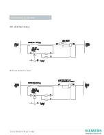
Physically check the wiring to the relay terminals for se-
curity and that is correct to the circuit schematic/wiring
diagrams.
Using a 500V insulation test set:
a) Connect all relay terminals together and measure the
resistance to earth
b) Connect the d.c. input terminals together and measure
the resistance between these terminals and all other
terminals connected together and to earth.
c) Connect the relay output contacts together and meas-
ure the resistance between these terminals and all other
terminals connected together including earth.
A value of 2.5 to 3.0 megohms obtained from the above
tests is considered satisfactory, a value of less than 1.0
megaohm is not satisfactory and the cause of such a low
reading should be determined and corrected.
It should not be necessary to adjust settings during rou-
tine tests unless parts have been replaced or other repairs
carried out. Adjustment of one setting will often influ-
ence another, therefore all settings must be checked after
the final adjustment.
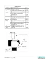
The table of Mechanical Settings provides the basic set-
tings necessary before finally setting the relay to obtain
its performance and are generally minimum values.
Contact tips are fine silver on copper and should only be
burnished if any pitting has occurred. Contact pressures
are set by gentle pressure with contact setting pliers
near to the contact stack assembly. During this operation
avoid putting any stress on the contact actuating cone.
Contact pressures should be measured using an
accurate gram gauge at the tip of the contact leaf.
Description
Unpacking, handling & storage
Safety
Preliminary Tests
Insulation Tests
Mechanical Settings
Contacts


