On-Line Operation
UMSITRPDS3-1
November
2010
6-18
6.3 LOCAL OPERATION WITHOUT A DISPLAY OR WITH ACTIVATED KEYLOCK
When a transmitter is ordered without a display, pushbutton disable mode LS is the default setting.
Limited operation from the magnetic pushbuttons is available. This section describes local operation
when the display is not present or when the magnetic pushbuttons or several modes have been disabled.
Refer to Section 6.2.8 for the pushbutton and function disable options. To cancel magnetic pushbuttons
disable, refer to Section 6.2.1. In most instances, it will be possible to set zero and full scale, as described
in the section below.
6.3.1 Set Zero and Full Scale
The differences between set and adjust were discussed in Section 6.2.2.1. The same conditions and
mathematical relationships apply whether operating with or without a display.
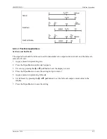
Use the following procedure to set the output current for zero to 4 mA and the full scale to 20 mA.
1.
Apply a reference pressure corresponding to zero.
2.
Press both arrow pushbuttons simultaneously so that the output is set to 4 mA.
3.
Press the M pushbutton to save the setting.
4.
Apply a reference pressure corresponding to full scale.
5.
Press both arrow pushbuttons simultaneously so the output is set to 20 mA.
6.
Press the M pushbutton to save the setting.
If the output current is not set but adjusted continuously, the currents will need to be calculated; refer to
Section 6.2.2.1 as needed. It is possible to make an adjustment for zero, full scale, or for both values.
Содержание 7MF4033 series
Страница 48: ...Model 275 Universal Hart Communicator UMSITRPDS3 1 November 2010 2 26 ...
Страница 86: ...Installation UMSITRPDS3 1 November 2010 4 34 ...
Страница 152: ...Calibration and Maintenance UMSITRPSD3 1 November 2010 7 20 ...
Страница 158: ...Circuit Description UMSITRPDS3 1 November 2010 8 6 ...
Страница 197: ......
Страница 198: ......
Страница 200: ...Model Designations and Specifications UMSITRPDS3 1 November 2010 9 42 ...
Страница 204: ...Glossary UMSITRPDS3 1 November 2010 10 4 ...
Страница 208: ...Appendix A Online Configuration Map UMSITRPDS3 1 11 4 November 2010 ...
Страница 210: ...Appendix B Hazardous Area Installation UMSITRPDS3 1 12 2 November 2010 FIGURE 12 1 Control Drawing ...
Страница 211: ...UMSITRPDS3 1 Appendix B Hazardous Area Installation November 2010 12 3 FIGURE 12 2 Control Drawing ...
Страница 212: ...Appendix B Hazardous Area Installation UMSITRPDS3 1 12 4 November 2010 FIGURE 12 3 Control Drawing ...
Страница 216: ...Appendix C Elevation and Suppression Correction UMSITRPDS3 1 13 4 November 2010 ...


