


Connecting
3.1 Terminal assignment
CPU 1513R-1 PN (6ES7513-1RL00-0AB0)
Equipment Manual, 05/2021, A5E42009333-AC
27
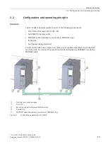
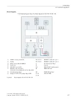
Block diagram
The following figure shows the block diagram of the CPU 1513R-1 PN.
①
SIMATIC memory card (X50)
PN X1 P1 R
PROFINET interface X1 port 1
②
Display
PN X1 P2 R
PROFINET interface X1 port 2
③
Mode selector RUN/STOP/MRES
L+
24 V DC supply voltage
④
Electronics
M
Ground
⑤
PROFINET 2-port switch
R/S
RUN/STOP LED (yellow/green)
⑥
Backplane bus connection
(connection to backplane bus not configurable)
ER
ERROR LED (red)
⑦
Internal supply voltage
MT
MAINT LED (yellow)
⑧
Supply of the 24 V DC supply voltage (X80)
X1 P1,
X1 P2
LED Link TX/RX
Figure 3-2
Block diagram of the CPU 1513R-1 PN
Содержание 6ES7513-1RL00-0AB0
Страница 1: ......