background image

Assembly and Installation Information

SIPART DR22/DR24

C79000-M7474-C38-01

18

5.4

Insertion of Modules

The modules are inserted from the rear side of the device and locked.

Important:

-

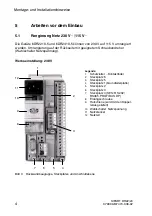
See Figure 2 for the slots.

-

The slots are coded.

-

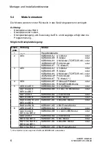
The slot layout and the allocation of the inputs and outputs are assigned by

programming.

Possible slot layout:

Slot

Action

Module

1

--------

main circuit board

2

AE4

6DR2800-8J U/I module

or

6DR2800-8R R module

or

6DR2800-8V UNI module (TC/RTD/R/mV) or

(6DR2800-8P Pt100 module

or

6DR2800-8T TC module) *)

3

AE5

6DR2800-8J U/I module

or

6DR2800-8R R module

or

6DR2800-8V UNI module (TC/RTD/R/mV) or

(6DR2800-8P Pt100 module

or

6DR2800-8T TC module *)

4

SES

6DR2803-8P Profibus DP module

or

6DR2803-8C RS232/RS485 module

5

AE9 to AE11

6DR2800-8A 3 x U/I module

or

AA7 to AA9

BE5 to BE7

6DR2802-8B 3 x AA/ 3 x BE module

or

AA7 and St

6DR2802-8A y-hold module

or

BE5 to BE9

6DR2801-8C 5 BE module

or

BA9 to BA12 and

BE5 to BE6

6DR2801-8E 4 BA/2BE module

or

BA9 to BA10

6DR2801-8D 2 BA relay module

6

AE6 to AE8

6DR2800-8A 3 x U/I module

or

AA4 to A6

BE10 to BE12

6DR2802-8B 3 x AA/3 x BE module

or

AA4 and St

6DR2802-8A y-hold module

or

BE10 to BE14

6DR2801-8C 5 BE module

or

BA13 to BA16 and

BE10 to BE11

6DR2801-8E 4 BA/2BE module

or

BA13 to BA14

6DR2801-8D 2 BA relay module

*) We recommend the installation of the UNI module 6DR2800-8V.

Содержание 6DR2210-4

Страница 1: ...d Installation Information C79000 M7474 C38 02 SIPART DR22 SIPART DR24 Regler Controller Regler Controller 6DR2210 4 5 6DR2410 4 5 Deutsch Seite 1 English Page 13 Regler SIPART DR22 SIPART DR22 controller Regler SIPART DR24 SIPART DR24 controller ...

Страница 2: ...echte vorbehalten insbesondere für den Fall derPatentertei lung oder GM Eintragung Technische Änderungen vorbehalten Copying of this document and giving it to others and the use or communication of the contents thereof are forbidden without express authority Offenders are liable to the payment of damages All rights are reserved in the event of the grant of a patent or the registration of a utility...

Страница 3: ...zspannung 10 7 3 Beschaltung Signalumformer 10 7 4 Gerät an die Versorgungsspannung anschließen 11 1 Allgemeine Hinweise Die Montage und Installationshinweise versetzen Sie in die Lage die vorberei tenden Arbeiten sowie den elektrischen Anschluß des Grundgerätes auszuführen Weitergehende Informationen über das Parametrieren und Strukturieren sowie über die Beschaltung der Signalumformer finden Sie...

Страница 4: ...eten An diesem Gerät sollte deshalb nur qualifiziertes Personal arbeiten 3 Lieferumfang Im Lieferumfang sind enthalten 1 Regler entsprechend der Bestellung 1 Kaltgerätestecker für 230 V 115 V oder ein Spezialstecker für Hilfsenergie UC 24V 2 Spannelemente steckbar 1 Anleitung Montage und Installationshinweise Steckbare Schraubklemmen für die Anschlüsse des Grundgerätes Grundgeräte Bestellnummer Ne...

Страница 5: ...AE3 potentialfrei bis 10 V Gleichtakt Strom Nennsignalbereich Aussteuerbereich Eingangswiderstand Gleichtaktspannung 0 4 bis 20 mA 1 bis 21 mA 49 9 Ohm 0 bis 10 V Spannung Nennsignalbereich Eingangswiderstand 0 199 6 bis 998mV oder 0 2 bis 10V 200 KOhm Analogausgänge AA1 bis AA3 Nennsignalbereich Bürdenspannung potentialgebunden 0 4 bis 20 mA ab 1 bis 18V Binäreingänge Signalzustand 0 Signalzustan...

Страница 6: ...gnetem Schraubendreher Wahlschalter Netzspannung Werkseinstellung 230 V Legende 1 Schutzleiter Kontaktfeder 2 Steckplatz 6 3 Steckplatz 5 4 Steckplatz 1 Grundleiterplatte 5 Steckplatz 2 6 Steckplatz 3 7 Steckplatz 4 SES RS 232 RS485 PROFIBUS DP 8 Erdungsschraube 9 Hutschiene wird mit den Koppel relais geliefert 10 Wahlschalter Netzspannung 11 Netzstecker 12 Netzteil 1 12 11 10 9 8 3 7 6 5 4 2 Bild...

Страница 7: ...g Meßstellenschild entnehmen 1 2 Befestigungsschraube lösen 1 3 Frontbaugruppe herausnehmen und Steckverbinder zur Grundleiterplatte lösen 2 Grundleiterplatte von der Rückseite entriegeln mit geeignetem Schrauben dreher und nach hinten aus dem Gehäuse herausziehen 3 Einstellungen auf der Grundleiterplatte vornehmen siehe Bild 3 4 Grundleiterplatte wieder einsetzen und verriegeln 5 Frontbaugruppe w...

Страница 8: ...800 8V UNI Modul TC RTD R mV oder 6DR2800 8P Pt100 Modul oder 6DR2800 8T TC Modul 4 SES 6DR2803 8P Profibus DP Modul oder 6DR2803 8C RS232 RS485 Modul 5 AE9 bis AE11 6DR2800 8A 3 x U I Modul oder AA7 bis AA9 BE5 bis BE7 6DR2802 8B 3 x AA 3 x BE Modul oder AA7 und St 6DR2802 8A y hold Modul oder BE5 bis BE9 6DR2801 8C 5 BE Modul oder BA9 bis BA12 und BE5 bis BE6 6DR2801 8E 4 BA 2BE Modul oder BA9 b...

Страница 9: ...chnittbreite b 2 140 1 3 212 1 4 284 1 10 716 1 Bild 5 Abmessungen und Tafelausschnitt Vorgehensweise 1 Schieben Sie den Regler von vorn in den vorbereiteten Tafelausschnitt ein 2 Rasten Sie die beiden Spannstücke in die dafür vorgesehenen Öffnungen auf der Reglerober und Reglerunterseite ein 3 Drehen Sie die Gewindestangen in den Spannstücken solange ein bis der Regler sicher in der Tafel befesti...

Страница 10: ...Montage und Installationshinweise SIPART DR22 24 C79000 M7474 C38 02 8 7 Elektrischer Anschluß 7 1 Beschaltung Grundgerät Bild 6 Blockschaltbild SIPART DR22 ...

Страница 11: ...Montage und Installationshinweise SIPART DR22 DR24 C79000 M7474 C38 02 9 Bild 7 Blockschaltbild SIPART DR24 ...

Страница 12: ...mme 1 7 Dy auf BA2 Klemme 1 5 7 2 Verhalten des Gerätes nach dem Zuschalten der Netz spannung WARNUNG Bei Inbetriebnahme des Gerätes können je nach Konfigurierung und letzter Betriebsart Stellgrößen ausgegeben werden die Störun gen im aktuellen Prozeß hervorrufen könnten Bei sicherheitsrelevanten Anlagen sollten Sie vor dem ersten Einschalten des Netzes Informationen über die Konfigurierung und le...

Страница 13: ...AC L N PE Bild 8 Beschaltung Hilfsenergie 230 V 115 V D 6DR2210 5 6DR2410 4 UC 24 V 2 pol Spezialstecker Polung beliebig weitere Verbraucher des gleichen Kreises ggf Sicherung vergrößern 6DR2210 4 6DR2410 4 pro Gerät T3 15 A 24 V UC 24 V 5 V UREF Bild 9 Beschaltung Hilfsenergie 24 V WARNUNG Zur Gewährleistung der hohen elektromagnetischen Verträglichkeit EMV muß die Schutzleiterschraube Erdungssch...

Страница 14: ...Montage und Installationshinweise SIPART DR22 24 C79000 M7474 C38 02 12 ...

Страница 15: ...se after Switching on the Power Supply 22 7 3 Wiring the Signal Converter 22 7 4 Connect Device to the Supply Voltage 23 1 General Information The assembly and installation information will enable you to perform the set up and the electrical connections on the basic device Further information about parameterization and structuring as well as the wiring of the signal converter can be found in the h...

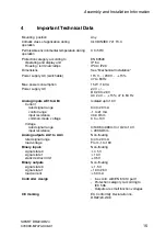
Страница 16: ...efore only qualified personal should work with this device 3 Scope of Supply The following items are supplied 1 controller corresponding to the order 1 power supply connector 230 V 115 V or one special connector for auxiliary power UC 24 V 2 clamping elements pluggable 1 assembly and installation information multi pin screw type terminal blocks for process signals Basic device Order number Power s...

Страница 17: ... V 15 47 to 63 Hz Analog inputs AE1 to AE3 Current rated signal range control range input resistance common mode voltage Isolated up to 10 V 0 4 to 20 mA 1 to 21 mA 49 9 Ohm 0 to 10 V Voltage rated signal range input resistance 0 199 6 to 998 mV or 0 2 to 10 V 200 KOhm Analog outputs AA1 to AA3 rated signal range load voltage Non floating 0 4 to 20 mA From 1 to 18V Binary inputs signal state 0 sig...

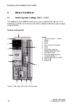
Страница 18: ... the rear side with a suitable screwdriver power supply selector switch Factory setting 230V Figure 2 Legend 1 ground conductor contact spring 2 slot 6 3 slot 5 4 slot 1 main circuit board 5 slot 2 6 slot 3 7 slot 4 SES RS 232 RS485 PROFIBUS DP 8 grounding screw 9 DIN rail supplied with the connecting relay 10 power supply selector switch 11 power plug 12 power unit 1 12 11 10 9 8 3 7 6 5 4 2 Figu...

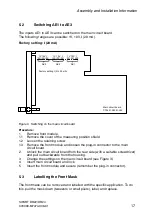
Страница 19: ...Remove the cover of the measuring position shield 1 2 Loosen the retaining screw 1 3 Remove the front module and loosen the plug in connector to the main circuit board 2 Unlock the main circuit board from the rear side with a suitable screwdriver and pull out backwards from the housing 3 Change the settings on the main circuit board see Figure 3 4 Insert main circuit board and lock 5 Insert the fr...

Страница 20: ... or 6DR2800 8V UNI module TC RTD R mV or 6DR2800 8P Pt100 module or 6DR2800 8T TC module 4 SES 6DR2803 8P Profibus DP module or 6DR2803 8C RS232 RS485 module 5 AE9 to AE11 6DR2800 8A 3 x U I module or AA7 to AA9 BE5 to BE7 6DR2802 8B 3 x AA 3 x BE module or AA7 and St 6DR2802 8A y hold module or BE5 to BE9 6DR2801 8C 5 BE module or BA9 to BA12 and BE5 to BE6 6DR2801 8E 4 BA 2BE module or BA9 to BA...

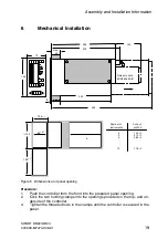
Страница 21: ... 1 b 145 Number of Cut out instruments width b 2 140 1 3 212 1 4 284 1 10 716 1 Figure 5 Dimensions and panel opening Procedure 1 Push the controller from the front into the prepared panel opening 2 Click the two holding clamps into the openings provided on the top and un derside of the controller 3 Tighten the threaded rods in the clamps until the controller is secured in the panel ...

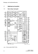
Страница 22: ...Assembly and Installation Information SIPART DR22 DR24 C79000 M7474 C38 01 20 7 Electrical Connection 7 1 Wiring the basic device Figure 6 Block diagram SIPART DR22 ...

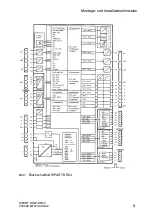
Страница 23: ...Assembly and Installation Information SIPART DR22 DR24 C79000 M7474 C38 01 21 Figure 7 Block diagram SIPART DR24 ...

Страница 24: ...minal 1 7 Dy on BA2 terminal 1 5 7 2 Device Response after Switching on the Power Supply WARNING When starting up the device depending on the configuration and the last type of operation it is possible that values will be output that could cause malfunctions in the current process With installations where safety is important information about the configuration and the last type of operation should...

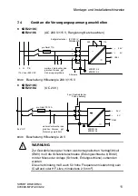
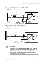
Страница 25: ...ring of the auxiliary power supply 230 V 115 V D 6DR2210 4 6DR2410 4 UC 24 V Double pole special plug any polarity 6DR2210 4 6DR2410 4 24 V UC 24 V 5 V UREF Other users on the same circuit increase fuse power slightly per device T3 15A Figure 9 Wiring of the auxiliary power supply 24 V WARNING To guarantee high electromagnetic compatibility EMC the ground conductor screw grounding screw 8 Figure 2...

Страница 26: ...Assembly and Installation Information SIPART DR22 DR24 C79000 M7474 C38 01 24 ...

Страница 27: ......

Страница 28: ...7474 C38 Printed in France Siemens AG Bereich Automatisierungs und Antriebstechnik Geschäftsgebiet Prozessinstrumentierung und Analytik D 76181 Karlsruhe Siemens Aktiengesellschaft E Siemens AG 1998 All rights reserved ...

Отзывы: