Инструкция по использованию Siemens 15-GMI-1000 доступна для бесплатного скачивания на нашем сайте. Объясняет функции и настройки устройства. Незаменимая помощь для правильной работы и обслуживания. Скачайте руководство сейчас на manualshive.com.
Courtesy of NationalSwitchgear.com
Страница 1: ...SIEMENS 5kVand 15kV Vacuum Circuit Breakers Type GMI Instruction Installation Operation Maintenance SG 3268 01 Courtesy of NationalSwitchgear com ...
Страница 2: ... the Secondary Disconnect Automatic Spring Charging Check Control Power Required Electrical Close and Trip Check Control Power Required Checks of the Spring Charging Motor High Potential Tests Electrical Vacuum Integrity Check High Potential Test Equipment Vacuum Integrity Test Procedure As Found Insulation Tests Test Equipment As Found Test Procedure Inspection and Cleaning of Breaker Insulation ...
Страница 3: ...i Pump Relay Device 52Y Replacement of the Auxiliary Switch Replacement of Motor Cut Off Switch Device LS1 and Spring Charged Reset Switch LS2 32 Replacement of Trip Latch Reset Check Switch Device LS3 Replacement of Racking Position Switch Device LS4 Figure 59 Replacement of Dashpot Assembly 30 33 30 30 33 30 34 36 31 31 Annual inspection Tasks 37 32 Troubleshooting 38 Appendix Table A 1 Type GMI...
Страница 4: ...rsons thoroughly familiar with the equipment instruction manuals and drawings Dangerous Procedures Qualified Person In addition to other procedures described in this manual as dangerous user personnel must adhere to the following 1 Always work on a de energized breaker Always de energize a breaker and remove it from the metal clad switchgear before performing any tests maintenance or repair 2 Alwa...
Страница 5: ...ery receipt and acknowledged with driver s signature Notation Pos sible internal damage subject to inspection must be on delivery receipt 3 Notify Siemens Sales office immediately of any shipment damage 4 Arrange for carrier s inspection Do not move the unit from its unloading point 4 The palleted circuit breaker can also be moved using a properly rated fork lift vehicle The pallets are designed f...
Страница 6: ... are normally shipped with their primary contacts open and their springs discharged How ever it is critical to first verify the discharged condition of the spring loaded mechanisms after de energizing control power De Energizing Control Power in Switchgear Mounted Circuit Breakers When the circuit breaker is mounted in switchgear open the control power disconnect device in the metal clad switchgea...
Страница 7: ...e circuit breaker is then free to be rolled out using the handles as shown in Figure 4 The wheels of the circuit breaker are virtually at floor level and one person can easily handle the unit Removal from Upper Cell Indoor and Shelter Clad Outdoor Switchgear Removal of the upper breaker in a two high assembly is similar to removal of a breaker from a lower cell with several additional steps Figure...
Страница 8: ...er Extension Rails WARNING Movement of breaker out from disconnect position without extension rails can cause severe equipment damage and personal injury 4 Move the breaker release latch to the left The breaker is then free to be rolled out on the two support rails using the handles 5 Remove the breaker from the two extension rails using the approved Siemens breaker lifting device 6 Lift the two e...
Страница 9: ...ecting Split Plug Jumper to Circuit Breaker The automatic spring charging features of the circuit breaker must be checked Control power is required for automatic spring charging to take place 1 Open control power circuit by removing pullout fuse holder shown in Figure 1 2 Install breaker end of split plug jumper if furnished shown in Figure 7 to the circuit breaker The plug jumper is secured by me...
Страница 10: ... and contact fingers shown in Figure 9 Verify mechanical condition of finger springs and the disconnect studs 3 Coat movable primary contact fingers Figure 9 and the secondary disconnect contacts Figure 24 with a light film of Siemens Contact Lubricant No 15 171 370 002 4 The GMI vacuum circuit breaker is ready for installation into its assigned cubicle of the metal clad switchgear Refer to remova...
Страница 11: ...reaker I Figure 11 Rear View of GMI Breaker lished The interrupter stationary contact is connected to the upper disconnect stud of the circuit breaker The interrupter movable contact is connected to the lower disconnect stud and driving mechanism of the circuit breaker The metal bellows assembly provides a secure seal around the mov able contact preventing loss of vacuum while permitting vertical ...
Страница 12: ...se to phase These four plates of glass polyester insulating material are attached to the circuit breaker housing and provide suitable electrical insulation between the vacuum interrupter primary circuits and the housing Figure 14 Breaker with Insulating Outer Phase Barriers Stored Energy Operating Mechanism The stored energy operating mechanism of the GMI circuit breaker is an integrated arrangeme...
Страница 13: ...corresponding to the breaker open with the closing springs discharged Fig ure 15 and charged Figure 16 Figure 17 showsportions of the operator mechanism that manually or electrically Figure 16 Breaker Open Closing Springs Charged charge the closing springs The drive cam 20 the closing spring crank arms see Figure 19 and spring condition indicator cam 18 are directly keyed to the main cam shaft 3 T...
Страница 14: ...se hatchet 22 will be released by this rotation allowing the main cam shaft 3 to be driven by the closing springs Depressing the manual close button on the operator panel causes the rotation of the close shaft 72 by the lower end of the close shaft actuator 75 Rotation of the main cam shaft 3 in a manual closing operation is identical to that of an electrical closing opera tion As the main cam sha...
Страница 15: ...n of the piston creates an opposing force controlling the opening speed of the circuit breaker The dashpot push rod is connected to the jack shaft by a crank linkage by charging status of the closing springs or position of the drive cam 20 Rapid Auto Reclosing Mode The closing springs are automatically recharged by the motor driven operating mechanism when the breaker has closed The operating mech...
Страница 16: ...rcharging h Manual charging action must be suspended when the operator sees the charged status appear on the front panel of the circuit breaker and hears the sound of impact against the internal closing latch Figure 22 Spring Charging Motor The motor control circuits call for automatic charging of the springs by the motor whenever control power is available and the springs are discharged The sprin...
Страница 17: ...us indicators are also connected to this same disconnect block Figure 23 Close Top and Trip Bottom Solenoids The anti pump relay shown in Figure 55 electrically iso lates signals to the close solenoid such that only one releas ing action by the close solenoid can occur during each application of the close command The circuit breaker must be tripped the springs recharged and the closing signal remo...
Страница 18: ...tches are provided in the switchgear only when specified The breaker engages the MOC auxiliary switch only in the connected operating position unless an optional test posi tion pickup is specified in the contract If a test position pickup is included the breaker will engage the auxiliary switch in both positions Figure 28 Up to 24 stages may be provided TOC Truck Operated Cell Switch Figure 29 sho...
Страница 19: ...sing or tripping the circuit breaker can be manually charged closed and tripped without external control power Figure 32 is a standard wiring diagram of the circuit breaker operating from dc control power All of the device symbols are the same as shown in the schematic diagram Limit Switches Figure 30 The motor cutoff switch LS1 is used to sense the position of the driven mechanisms This switch de...
Страница 20: ...ge continuous current interrupting and momentary ratings and will not allow breaker insertion unless they match or exceed the cell rating The frame of the GMI circuit breaker contains several im portant devices and features deserving of special attention These are the ground disconnect the four racking wheels and four handling wheels Ground Disconnect Figure 35 shows the ground disconnect contact ...
Страница 21: ...HEN BRK IS OPEN 52Y ANTI PUMP RELAY 52T OPENING SOLENOID TRIP 52SRC SPRING RELEASE SOLENOID CLOSE 88 SPRING CHARGING MOTOR SD SECONDARY DISCONNECT 01 C CONTROL SWITCH CLOSE 01 T CONTROL SWITCH TRIP R RED INDICATING LAMP G GREEN INDICATING LAMP W WHfTE INDICATING LAMP WIRE CHART WIRE TERMINALS AUX SWITCH 5 2Y 5 8 6 1 ee 2 SOI LSI NO S015 SOI 5 SOI 3 SD 1 3 TYPICAL REMOTE DEVICES 5A 3 1 6 Y 1 3 L S ...
Страница 22: ...in type outdoor switchgear Figure 33 Typical Trip Free Interlock On indoor and Shelter Clad switchgear with circuit breakers located in the lower cell the circuit breaker is easily rolled out of the switchgear by a single person When circuit breakers are located in the upper cells handling of the k Figure 36 Ground Bar in Switchgear Figure 34 Rating Interlock Interference Plates Courtesy of Nation...
Страница 23: ...ratings 4 They prevent closing of the circuit breaker unless it is in either the Test or Connect position Racking Mechanism Figure 38 shows the racking mechanism in the switchgear used to move the circuit breaker between the Disconnect Test and Connected positions This mechanism contains a set of interface blocks that mate with the bottom of the circuit breaker housing and lock the breaker to the ...
Страница 24: ...Removal from Switchgear Read instruction manual observe safety instructions and limit use to qualified per sonnel Prior to performing any inspection checks or tests the circuit breaker must be removed from the switchgear The Instal lation and Initial Functional Tests section describes the removal procedure in detail Principal steps are repeated here for information and guidance but without the det...
Страница 25: ...tential tests These instructions follow the recommendation that these tests contact erosion manual spring charging check and vacuum integrity high potential tests will be combined as described Cleanliness Check Figure 41 is a side view of the GMI circuit breaker with one of the side insulating panels removed tor show the vacuum interrupter and the upper and lower primary disconnects All of these c...
Страница 26: ...The contact erosion check of the vacuum interrupter is also performed during these tasks Cleaning and Lubrication Table 2 Lubrication Schedule ANSI C37 06 Table 8 Usual Service Conditions Maintenance Based Upon Number of Breaker Closing Operations Figure 41 View of Breaker Showing Vacuum Interrupters and Primary Disconnects Number of Closing Operations Breaker Type 5 GMI 350 15 GMI 1000 1 000 All ...
Страница 27: ...haft operating shaft by a pushrod linkage Clean the entire stored energy operator mechanism with a dry lint free cloth Check all components for evidence of excessive wear Place special attention upon the closing spring cranks and the various pushrods and linkages Figure 44 Front View of Operator Mechanism Lubricate all non electrical moving or sliding surfaces with a light coat of machine oil cont...
Страница 28: ...aker trips the condition of the dashpot and its internal piston rings is acceptable Check the dashpot mechanical linkages for smooth opera tion at the same time tion of acceptable contact condition is checked by the visibility of the erosion mark shown in Figure 46 The contact erosion check procedure is Be sure the breaker primary contacts are Closed Observe the erosion mark Figure 46 of each pole...
Страница 29: ...tion entitled Installation Checks Initial Functional Tests Primary tasks of this check are 1 The breaker is energized with control power for this check 2 De energize the source of control power Figure 1 3 Install the breaker end of the split plug jumper over the secondary disconnect of the circuit breaker The split plug jumper has one male and one female connector and cannot be installed incorrect...
Страница 30: ...ntact status indicator 2 As soon as the breaker has tripped the automatic spring charging process is repeated 3 After a satisfactory close operation is verified move the switchgear Close Trip switch to the Trip position Verify by both sound and contact position that the contacts are open Completion of these checks demonstrates satis The next series of tests involve use of high voltage test equipme...
Страница 31: ...Ac i e either 14 or 27 kV or Dc i e either 20 or 38 kV high potential test voltage between a primary conductor of the pole and ground for one minute 4 If no disruptive discharge occurs the insulation system is satisfactory 5 After test ground both ends and the middle of each vacuum bottle to dissipate any static charge 6 Disconnect the leads to the spring charging motor 7 Connect all points of the...
Страница 32: ...s shown in Figure 51 3 Clean barriers and post insulators using clean rags and one of the following cleaning solvents Soap and water Either No 1 or No 2 denatured alcohol White kerosene Varsol No 2 VM Naptha Either isopropyl or isobutyl alcohol Figure 51 Rear View Showing Outer Phase Barriers CAUTION Do not use any cleaning compounds con taining chlorinated hydrocarbons such as trichlorethylene pe...
Страница 33: ...the GMI vacuum circuit breaker WARNING All replacement of breaker components must be performed with the breaker com pletely de energized the springs dis charged Circuit Breaker Overhaul Table 5 lists the recommended overhaul schedule for GMI circuit breakers operating under ANSI usual conditions When actual operating conditions are more severe over haul periods should occur more frequently The cou...
Страница 34: ... 5 inches and when installed should be compressed to 6 88 inches screws which attach the close coil and the quick disconnect terminal for control leads The trip coil arrangement is similar Replacement of Anti Pump Relay Device 52Y Figure 55 helps illustrate the anti pump relay removal pro cedure The two nuts holding the relay and its mounting bracket are removed The wires connected to the relay m ...
Страница 35: ...lacement of the trip latch reset check switch is required both screws need to be removed Next mark both wires to the switch and remove them Then replace the switch rewire and reassemble the switch to the left hand mechanism side sheet Be sure to use the same washer and nut configuration as was present in the as shipped condition Figure 56 Replacement of Auxiliary Switch Replacement of Motor Cut Of...
Страница 36: ...s a complete assembly Check and replace as required Replacement of Primary Disconnect Fingers Figure 63 shows removal of the bolt which attaches the primary disconnect finger assembly to the primary discon nect With this bolt removed the finger assembly can be slid off the retaining arm as a unit Replace burnt fingers or broken springs as necessary Replacement of Vacuum Interrupters The following ...
Страница 37: ...d to withstand years of vertical movement However caution should be exercised in subjecting the bellows to ex cessive torque during removal and re placement Twisting the bellows through careless bolt removal or tightening may damage the vacuum interrupter Vacuum Interrupter Removal Steps for removal of the vacuum interrupter are 1 Remove the two X Clips holding the bell crank to the push rod shown...
Страница 38: ...equence of each spacing and lock washer Use two socket wrenches to hold both the head and nut end of the clamp that connects the flexible shunt to the movable contact There are holes on both sides of the lower stab support to permit insertion of sockets that will prevent twisting of the movable contact bellows when removing the movable contact bolt While holding both socket wrenches in place at th...
Страница 39: ... is properly seated to the base of the interrupter s movable contact Use two socket wrenches to tighten the clamp nut Tighten the nut to produce a torque per Table 6 Use of holding and torquing wrenches will prevent twisting the movable contact bellows 8 While maintaining use of the two wrenches at the flexi ble shunt tighten the bottom bolt into the movable contact Use the same torquing values li...
Страница 40: ...closing and tripping 1 Evidence of excessive wear 2 Lubrication of wear points 1 Mechanical damage or abrasion 1 Tightness and absence of mechanical damage 1 Automatic charging Fasteners Manual spring check Lubrication Electrical controls Wiring Terminals and connectors Close and trip solenoids anti pump relay auxiliary switches secondary disconnect 2 Close and trip with control power 1 Replace br...
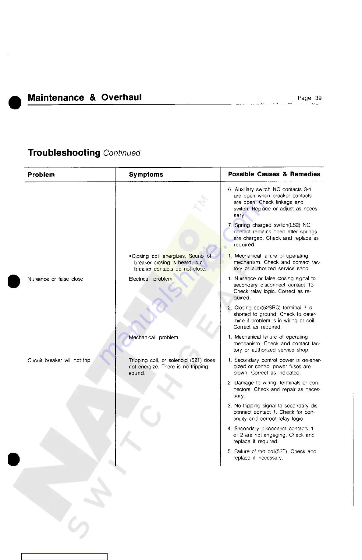
Страница 41: ...osing springs or tie bar assembly Check and replace as required 7 Mechanical failure of operating mechanism Refer to factory or authorized service shop Breaker fails to close Closing springs charge but breaker does not close Closing coil or solenoid 52SRC fails to energize No sound of breaker closing 1 Secondary control circuit de ener gized or control circuit fuses blown Correct as indicated 2 No...
Страница 42: ...ng or coil Correct as required 1 Mechanical failure of operating mechanism Check and contact fac tory or authorized service shop 1 Secondary control power is de ener gized or control power fuses are blown Correct as indicated 2 Damage to wiring terminals or con nectors Check and repair as neces sary 3 No tripping signal to secondary dis connect contact 1 Check for con tinuity and correct relay log...
Страница 43: ... open i e they remain closed Tripping coil 52T energizes Trip ping sound is heard but breaker con tacts do not open 1 Mechanical failure of operating mechanism Check and contact fac tory or authorized service shop 2 One or more of the vacuum inter rupters are held closed Check and replace as necessary 1 Tripping signal remains energized on secondary disconnect contact 1 Check for improper relay lo...
Страница 44: ...gavailable for specialapplication 2 Maximum voltage for whichthe breaker is designed and theupper limit for operation 3 K is the ratio of rated maximum voltage to the lower limit of the range of operating voltage in which the required symmetrical and asymmetricalinterruptingcapabilities vary in inverse proportionto theoperating voltage 4 3000ampereunits available withincreased fan cooledrating of ...
Страница 45: ... 10 6 120 VAC 104 127 104 127 10 6 3 240 VAC 6 14 208 254 208 254 Current at nominal voltage Table A 3 Interrupting Capacity Auxiliary Switch Contacts Continu ous Current Amperes Type Auxiliary Switch Control Circuit Voltage 120 Ac 240 Ac 48 Dc 125 Dc 250 DC Non inductive circuit interrupting capacity in amperes Breaker Auxiliary Switch TOC Auxiliary Switch MOC Auxiliary Switch 2 10 20 20 20 20 0 ...
Страница 46: ...I Siemens Energy Automation Inc Switchgear Division P O Box 29503 Raleigh NC 27626 919 365 6660 SIEMENS PRINTED iN U S A 02 90 2M Courtesy of NationalSwitchgear com ...