Courtesy of NationalSwitchgear.com
Страница 1: ...SIEMENS ALLIS I IM I O N S LOAD BREAK SWITCH INSTALLATION OPERATION MAINTENANCE TYPE LBS ICD 6028 01 20X3498 01 Courtesy of NationalSwitchgear com ...
Страница 2: ...ON SWITCH OPERATION AND ADJUSTMENT 7 TOUCH UP PAINT REPLACEMENT PARTS 7 4 4 8 4 8 4 i The information contained within is intended to assist operating per sonnel by providing information on the general characteristics of equipmentof this type Itdoes not relieve the userof responsibility touse sound Practices and Safety Procedures in the installation application operation and maintenance of the par...
Страница 3: ...ng properties The chute contains a pair ofsilver tungsten tipped restrainingcontactswhich engage the quick break blade when in the closed position The necessary spring pressure is supplied by a pair of phosphor bronze compression springs inside the arc chute GENERAL INFORMATION This instruction book is to acquaint the purchaser user with the Siemens Allis Type LBS Load Break Switch In stallation a...
Страница 4: ...mpartments are in the open posi tion Key interlock systems are also available for safety se quence interlocking of compartment doors feeder circuit breakers isolating switches other load break switches etc Two key interlock units can be mounted and used simultaneously to provide increased system flexibility A key interlock mounted in the top location on the operator mechanism permits the switch to...
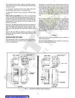
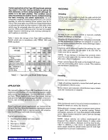
Страница 5: ...2300 5000 5000 4160 4800 1200 Continuous Ampere Rating Ampere Interrupting Capacity of Switch Fault Close Amps Asym Momentary Current Amps Max Transformer 3 Phase kva load KV BIL rating 450 450 450 600 600 600 600 1200 600 80 000 80 000 80 000 80 000 80 000 80 000 60 000 60 000 40 000 40 000 1500 2500 3000 60 60 60 60 60 TABLE 1 Type LBS Load Break Switch Ratings Uncrating Exercise care in uncrati...
Страница 6: ...gram Erection The load break switch cubicle must be mounted in a level position Install shims as required When only a single unit is being installed it should be securely anchored when properly set in place When multi ple units are being installed align the front of each unit with the first and bolt the units together before securely anchoring If the cubicle is not properly mounted difficulty may ...
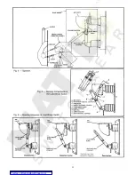
Страница 7: ... as shown in Fig 4 3 Grasp knob with right hand Tocloseswitch puli knob and move handle toa straight up position As the handle is moved the main moving contacts start to move and crank compresses spring in operator assembly When crank is over center spring takesover and closes switch independent of the speed of the handle Re verse motion of handle to open switch 4 Pull knob and move operating hand...
Страница 8: ...Fig 4 Operator Fig 5 Working Components of the Load Break Switch Fig 6 Opening Sequence of Load Break Switch 6 Courtesy of NationalSwitchgear com ...
Страница 9: ...aving overheated check for poor or loose connections or loose connections or for overloads 3 Check condition1 of main contacts quick break blades and arc chute Replace any worn or damaged parts 4 Check arc chutes for loose bolts and retighten if needed Check fastening of switch shaft assembly Apply grease to parts requiring lubrication 5 Apply high temperature lubricant silicon or molyb denum base...
Страница 10: ...the insulation is dry QUANTITY PER PART NUMBER DESCRIPTION SWITCH REPLACEMENT PARTS 3 Stationary Contact upper Stationary Contact lower Arc Chute Assembly Moving Contact Assembly 600A Includes movable arcing Contact Operating Link Contact Lubricant 25 205 109 002 25 205 109 004 18 375 793 501 18 376 028 502 Thefollowing list of parts represents the major components of the load break switch subject...
Страница 11: ... SIEMENS ALLIS INDUSTRIAL CONTROLS P O Box 89 Wichita Falls Texas 76307 Courtesy of NationalSwitchgear com ...