27
5996
8
2020
-
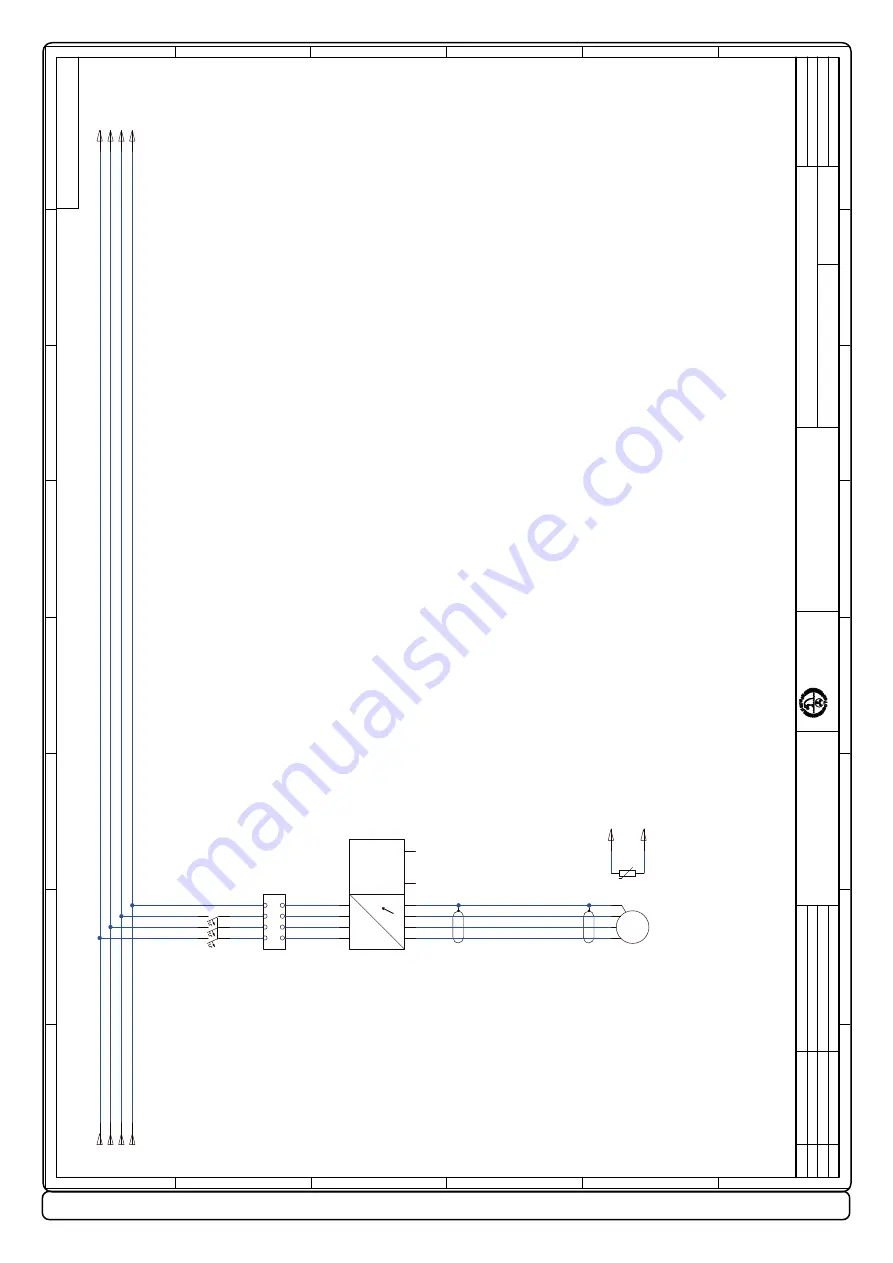
SAC 240 & SAC 320
MG_0010
P.O. Box 519
N-1612 Fredrikstad Tel: +47 69 30 00 60
Sleipner Motor
AS
Copyright all RIGHTS reserved Sleipner Motor
AS
P/N:
DWG No:
All Dimensions in mm
Drawn
Approved
Revised
Date
Name
Sheet
Sh.
Rev:
E
D
C
B
F
A
E
D
C
B
F
A
8
7
6
5
4
3
2
1
8
7
6
5
4
3
2
1
AC
3
SAC PDC 301 -
ACS580/ACH580
VFD Power
BS-013-EL-161
E
18.04.18
BS
07.01.20
SV
M
3
~
~
~~
~
T1
T2
-U2
L1
L2
L3
PE
1
2
3
4
5
6
Module Circuit Breaker 3P
-F1
L3
PE
L1
L2
L1
L2
L3
PE
U1
V1
W1
UDC+
UDC-
PE
U2
V2
W2
PE
ACS580/ACH580
-U1
AC Motor 3
-M1
1
2
U
V
W
PE
AC Motor 3
-M1
Temperature Sensor
Use shielded cable designed for use with variable frequency drives.
High voltage DC bus. Do not connect.
MG_0009
P.O. Box 519
N-1612 Fredrikstad Tel: +47 69 30 00 60
Sleipner Motor
AS
Copyright all RIGHTS reserved Sleipner Motor
AS
P/N:
DWG No:
All Dimensions in mm
Drawn
Approved
Revised
Date
Name
Sheet
Sh.
Rev:
E
D
C
B
F
A
E
D
C
B
F
A
8
7
6
5
4
3
2
1
8
7
6
5
4
3
2
1
PDC-301
3
SAC PDC 301 -
ACS580/ACH580
Control
BS-013-EL-161
E
18.04.18
BS
07.01.20
SV
Power Management System
Thruster
Enable
Power
Limit
Thruster
Request
Aux. voltage output and programmable digital inputs
Serial data link switches
Relay output RO2 [Running]
250V
AC /30V DC, 2A
Relay output RO1 [Ready run]
250V
AC /30V DC, 2A
EFB (EIA-485) / Embedded fieldbus
Safe torque o
ff
Reference voltage and analog inputs and outputs
RO2A
RO2C
DGND
+24V
AO1
AO2
AGND
RO3B
RO3A
RO3C
IN2
Panel Port
Relay output RO3 [Fault (-1)]
250V
AC /30V DC, 2A
BIAS
S5 (BIAS)
ON
S4 (TERM)
ON
TERM
X14
Option slot 2
X13
Option slot 1
Voltage/Current selection switches
U
S1
AI1 (U/I)
U
S2
AI2 (U/I)
I
S3
AO1 (U/I)
U
I
I
All control boards do not have switches S1, S2 and S3. In that case, select voltage or current for inputs AI1 and
AI2 and output
AO1 with parameters.
DI6
DI5
DI4
DI3
DI2
DI1
AGND
+10V
AI2
AGND
IN1
SGND
OUT2
OUT1
B+
RO2B
DCOM
SCR
AI1
A-
DGND
RO1B
RO1A
RO1C
SIDE-POWER
S-link
VFD
(RS-485)
-W2.X1
*5
T2
T1
6 1321
*5
*5
PMS
ACS580/ACH580
ACS580/ACH580
-U1
1
2
3
4
5
6
7
8
9
10
11
12
13
14
15
16
17
18
RJ45
34
35
36
37
38
29
30
31
19
20
21
22
23
24
25
26
27
X1
X2 & X3
X4
X5
X6
X7
X8
6 1326
-X1
PDC-301
-U4
Optional
Red Wire: Cut and Insulate
Ground the outer shield of the cable 360 degrees under the grounding clamp on the grounding shelf for the control cables inside VFD.
S-Link
WH
BU
BK


