


Chapter
12
Operating Instructions
UE4155
68
© SICK AG • Industrial Safety Systems • Germany • All rights reserved
8010178/TF82/2010-03-05
Subject to change without notice
Annex
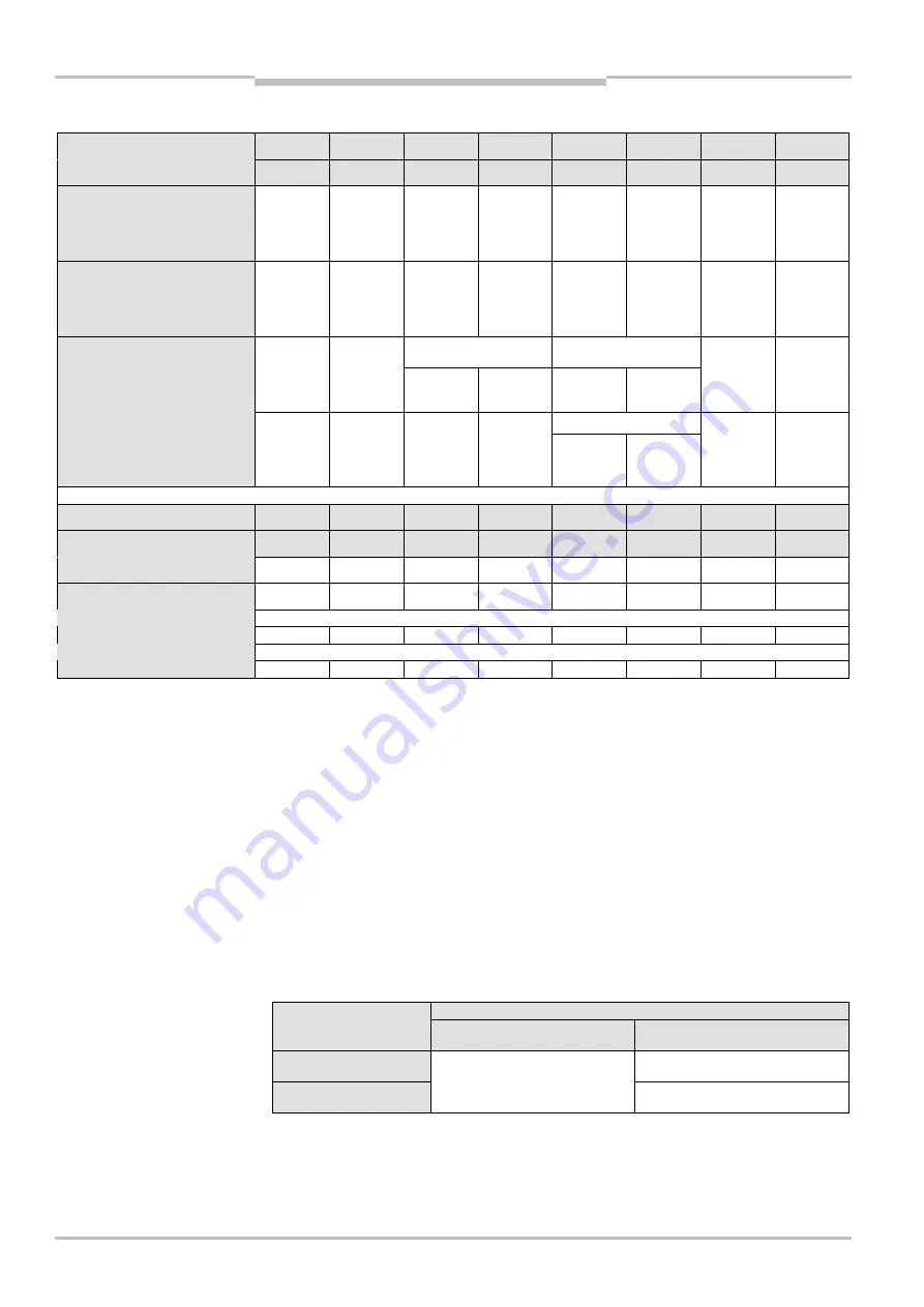
Input signals from the SDL connection to the FPLC
Address SDL1
2.7
2.6
2.5
2.4
2.3
2.2
2.1
2.0
Address SDL2
4.7
4.6
4.5
4.4
4.3
4.2
4.1
4.0
C4000 Standard/Advanced
Reset
required
RESET
(signal is
present)
Status
signal
output
(ADO)
Reserved
OSSD of
guest 2
green
OSSD of
guest 1
green
Host OSSD
green
OSSD
(output
signal sw.
device)
green
M4000 Advanced
Reset
required
RESET
(signal is
present)
Status
signal
output
(ADO)
Reserved
Additional
signal C1
or Belt stop
Muting
lamp
Off/On
Muting
status
OSSD
(output
signal sw.
device)
green
12
)
Simultaneously
monitored area
Used monitored area
S3000
Reset
required
RESET
(signal is
present)
Warning
14)
Protective
field free
14)
Warning
field free
14)
Protective
field free
14)
Warning
field free
14)
OSSD
(output
signal sw.
device)
green
12
)
Used monitored area
S300
Reset
required
RESET
(signal is
present)
Reserved
Reserved
Warning
field free
14)
Protective
field free
14)
Warning
field free
14)
OSSD
(output
signal sw.
device)
green
12
)
Address SDL1
3.7
3.6
3.5
3.4
3.3
3.2
3.1
3.0
Address SDL2
5.7
5.6
5.5
5.4
5.3
5.2
5.1
5.0
C4000 Standard/Advanced
Reserved
Reserved
Reserved
Reserved
Reserved
Reserved
Reserved
Reserved
M4000 Advanced
Reserved
Reserved
Reserved
Reserved
Reserved
Reserved
Reserved
Reserved
Status of the monitored-case inputs on the S3000
S3000
In D2
In D1
In C2
In C1
In B2
In B1
In A2
In A1
Status of the monitored-case inputs on the S300
15)
S300
Reserved
Reserved
Reserved
Reserved
In B2
In B1
In A2
In A1
Tab. 31: Process image of the input signals from the SDL connection to the FPLC
12)
Depending on the configuration of the bus node either the OSSD status read in via the hardware OSSD inputs
or the status received via SICK device communication is entered (see section “Reading the OSSD status at
the SDL connection“ on page 21).
13)
Warning:
The return value depends on the firmware version of the used S3000:
Return value
S3000 firmware version
Simultaneously monitored area
defined
Simultaneously monitored area
not defined
Controller 2.26 and
Interface 1.00
Permanently 1 (protective
field/warning field free)
Controllers < 2.26 and
Interface < 1.00
Status of the protective
field/warning field
Permanently 0 (protective
field/warning field free)
14)
Warning:
When an S3000 is used whose firmware version of the
controller < 2.26
and firmware version of
the
interfaces < 1.00
, only evaluate this bit in the FPLC together with the passive status of UE4155!
Reason: The bit operations for these devices are inverted (see above). The bit has the value 1 if a dangerous
state has been detected. The bit has the value 0 if no dangerous state has been detected. However, the bit
can also have the value 0 due to erroneous communication. For this reason, the passive status of UE4155
must always be monitored as well (for example for Siemens Step 7: variable PASS_OUT in the data block F
D
IO).
15)
In A1 to In D2 are the static control signals directly at the S3000 and S300.