- 11 -
3 HARDWARE INSTALLATION
Before removing or installing any of these devices including CPU, DIMMs, Add-On
Cards, Cables, please make sure to unplug the onboard power connector.
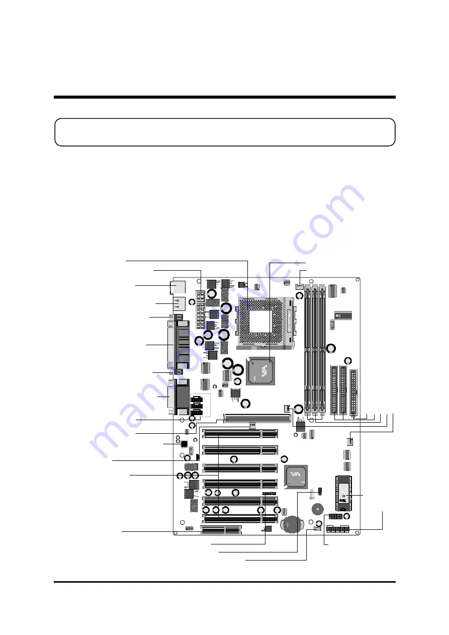
This section outlines how to install and configure your AK11 mainboard. Refer to the
following mainboard layout to help you identify various jumpers, connectors, slots, and
ports. Then follow these steps to guide you through a quick and correct installation of
your system.
3.1 Step-by-Step Installation
Accessories Of AK11
KEYBOARD & MOUSE
USB PORT
AGP 1
PCI 1
PCI 2
PCI 3
PCI 4
PCI 5
PCI 6
CNR
COM2
COM1 PRINT
AUDIO
J4
JP9
JP8
J1
LAN - WA KE
J2
V T8 2C 68 6B
0 02 1C G TA IW A N
1 3C ON3 40 0
1
1
J3
RST HLE D
PLED
+ -
+ - + -
SP EAK ER
GLED EP MIPWR BT
AW
AR
D
1999
P
C
I/P
N
P
K
7
20206
2269
JP10
JP11
JP12
CD_IN
TAD I/O
AUX
1
1
1
1
1
JP1
IR
1
JP
13
1
1
IDE1
1
IDE2
JP14
EX T USB PORT
1
JP2
1
FA N3
FA
N
4
FA
N
1
DIM1
DIM2 DIM3
FA
N2
1
1
Pa
na
soni
c
C
R2032
3V
JA
P
AN
1
ATXP WR
C
V
T
83
63A
00
50C
D
T
A
IW
A
N
2
IA
1
00
07
01
R T M 5 6 0 -1 4 1 R
1 2 0 5 2 Q 2 1 1 0 2
Pr
o
gr
am
m
ab
le
2
M
b
F
las
h
EE
P
R
O
M
PS2 Keyboard/
PS/2 Mouse Connectors
USB1/USB2Connectors
Socket 462
Serial Port Connector
(COM2)
Serial Port Connector
(COM1)
Parallel Connector
VIA 8363A Chipset
On Board Audio CODEC
IR Header -
JP1
On Board Audio Header-
JP10,JP11,JP12
AGP 2x/4x Slot
Six PCI Slots
CNR Slot
ATX Power Connector
FAN1
Line-In/Line-Out/Mic-In
Game/MIDI Connectors
Fl
op
py
C
on
ne
ct
or
Th
re
e D
IM
M
s
lot
s
Tw
o I
D
E C
onn
ec
to
rs
FA
N
4
FA
N
2
Fr
on
t Po
ne
l H
eade
r -
J3
Clear CMOS -
JP2
Wake-On-Lan Connector -
J2
Extended two USB
Connector -
JP14
FAN3


