background image

- 32 -

C1

!

!

!

!

!

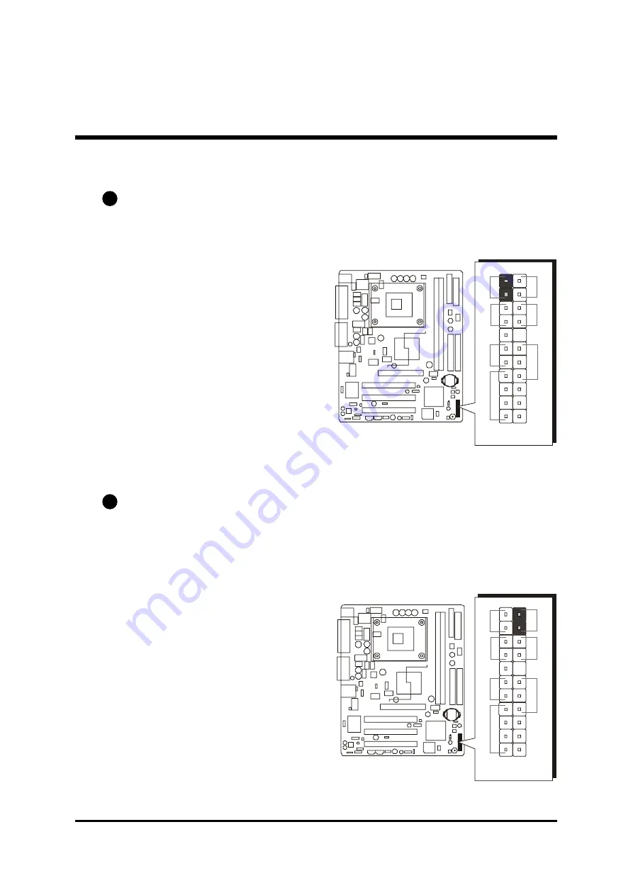
Front-Panel Connectors

HDD LED Connector (HLED)

Attach a connector cable from the IDE device LED to the 2-pin (HLED) header.
The HDD LED lights up whenever an IDE device is active.

Green LED Connector (GLED)

The Green LED (GLED) indicates that the system is currently in one of the power
saving modes (Doze/Standby/Suspend). When the system resumes to the nor-
mal operation mode, the Green LED will go off. Attach a 2-pin Green LED cable
to the GLED header.

C2

J P

 1

2

+

+

+

-

1

-

-

R

es

et

H

LE

D

G

LE

D

S

PE

AK

ER

E

PM

I

P

W

O

N

PL

E

D

12

+

+

+

-

1

-

-

R

es

et

H

LE

D

G

LE

D

S

PE

AK

ER

EP

M

I

PW

O

N

P

LE

D

Содержание MB48

Страница 1: ...MB48 MB48N MB50 MB50N Intel Pentium 4 Celeron 478 pin Processor with 400 533 MHz FSB Based DDR MAINBOARD User s Manual...

Страница 2: ...as been carefully checked for reliability however no guarantee is given as to the correctness of the contents In the interest of continued product improvement this company reserves the right to revise...

Страница 3: ...4 Install Internal Peripherals in System Case 14 STEP 5 Mount the Mainboard on the Computer Chassis 15 STEP 6 Connect Front Panel LEDs Switches Speaker USBs 16 STEP 7 Connect IDE and Floppy Disk Driv...

Страница 4: ...50N only 31 Front Panel Connectors HDD LED Connector HLED 32 Green LED Connector GLED 32 Hardware Reset Connector Reset 33 ATX Power On Off Switch Connector PWON 33 EPMI Connector EPMI 34 Power LED Co...

Страница 5: ...all VGA Driver 47 4 2 D Install Audio Driver 48 4 2 E Install LAN Driver MB48N MB50N only 49 4 2 F Install USB 2 0 Driver 50 4 3 View the User s Manual 51 5 BIOS SETUP 52 5 1 ENTER BIOS 52 5 2 THE MAI...

Страница 6: ...10 Jumper Settings A Closer Look Page 23 Software Utility How to Install Page 43 BIOS Setup How to Configure Page 52 About This Manual For First Time DIY System Builder Page 5 For Experienced DIY Use...

Страница 7: ...Settings and Chapter Chapter Chapter Chapter Chapter 4 Software Utility 4 Software Utility 4 Software Utility 4 Software Utility 4 Software Utility you will find how to work out your new mainboard Ch...

Страница 8: ...VGA Driver Audio Driver LAN Driver MB48N MB50N only MB48N MB50N only MB48N MB50N only MB48N MB50N only MB48N MB50N only USB 2 0 Driver Award Flashing Utility F W8 2 8 0 1 D B L 2 1 7 1 C 0 S L 6 6 K...

Страница 9: ...rovides jumper J2 to configure front side bus at 400 533MHz AC 97 Audio CODEC Supports 18 bit ADC and DAC resolutions and four analog line level stereo inputs Compliant with AC 97 2 2 specifications V...

Страница 10: ...legacy ATAPI devices ATAPI IDE CD ROM CD R CD RW and LS 120 supports ATX Power Supply Connector ATX power supply unit can be connected to the onboard 20 pin Pentium 4 standard ATX power connector and...

Страница 11: ...m ringing CPU Clock Setting CPU Clock Setting CPU Clock Setting CPU Clock Setting CPU Clock Setting This item allows users to adjust CPU host clock in BIOS CPU Multiplier Setting CPU Multiplier Settin...

Страница 12: ...ON Accessories Of MB48 N MB50 N FW8 28 01DB L 21 71C0 SL6 6K INTE L 01 C KOREA 22 AC8 YK H CT0 0 A MS1 1 1 7 02 27 22A C8 YK H CT 00 KB1 CN 1 AUX_IN CENTER BASS SPDIFExt PCI3 PCI2 PCI1 AGP ATX 12V CN...

Страница 13: ...the CPU installation Note the CPU orientation as you place it into the CPU socket 1 Pull up the CPU socket lever to 90 degree angle 2 Locate Pin 1 in the socket and look for a black dot or cut edge on...

Страница 14: ...a heatsink and fan if they are not bundled with your CPU Required is that install the set and plug its cable in the CPU fan power connector Note that there are kinds of CPU fan connectors Normally if...

Страница 15: ...ainboard con figuration procedures The factory set default settings are tuned for optimum system performance For advanced users who prefer to customize their system section 3 2 Jumper Settings 3 2 Jum...

Страница 16: ...by the manufacturer IDE HDD and CD ROM have to set jumpers to Master or Slave mode depending on whether you install more than one device of each kind 2 Connect the IDE cable and FDD cable on the back...

Страница 17: ...en the chassis and the mainboard The studs are used to fix the mainboard and to keep a certain distance between the them for avoiding any electrical shorts in between If your computer case is already...

Страница 18: ...ont panel LEDs switches speaker and USB connectors to JP12 JP7 and JP8 as shown below 1 HDD LED HLED 2 Green LED GLED 3 Hardware Reset Switch Reset 4 ATX Soft Power On Off PWON 5 Hardware System Manag...

Страница 19: ...Floppy Disk Drives 1 IDE cable connectors 2 Floppy cable connector Step 8 Connect Other Internal Peripherals 1 CD_IN AUX_IN and CENTER BASS connectors IDE1 IDE2 1 1 1 1 FDC AUX_IN CD_IN J 5 J 4 J 3 CD...

Страница 20: ...18 2 IR connector Step 9 Connect the Power Supplies 1 System power connectors IR JP 3 1 ATX 12V CN 2...

Страница 21: ...19 Step 10 Install Add On Cards in Expansion Slots 1 Accelerated Grapics Port AGP Card MB50 N only MB50 N only MB50 N only MB50 N only MB50 N only 2 PCI Card...

Страница 22: ...You are now ready to connect the external peripherals to your system s back panel 1 PS 2 Mouse and PS 2 Keyboard 2 Parallel Port 3 COM Port 4 VGA Port 5 MIDI Game Port 6 Audio Line Out Line In Mic In...

Страница 23: ...tended partition The FDISK utility will assign a drive letter i e C D E to each partition shown in the FDISK program After the FDISK procedure reboot your system by using the same disk Note Note Note...

Страница 24: ...stallation window on screen 2 Choose Install Mainboard MB48 N Software and complete it or 3 Choose Install Mainboard MB50 N Software and complete it 4 Choose Install Intel Chipset driver and complete...

Страница 25: ...m Jumpers with two pins capped are shown as for Close On or for Open Off To do this please place a plastic mini cap on the desired pair of pins Caution Caution Caution Caution Caution 1 Do not remove...

Страница 26: ...Expansion Slots Socket 478 CPU socket for Pentium 4 Celeron 478 pin processors DIMM1 2 Two DIMM slots for 128 256 512 MB and 1GB of 2 5V DDR SDRAM The total installed memory does not exceed 2GB AGP O...

Страница 27: ...MIDI GAME MIDI Game port USB USB1 USB2 ports LAN1 LAN port MB48N MB50N only MB48N MB50N only MB48N MB50N only MB48N MB50N only MB48N MB50N only Front Panel Connectors HLED HDD LED GLED Green LED Reset...

Страница 28: ...ystem fan connector JP3 IR header CN1 Wake On LAN connector J3 J4 Audio CD_IN connectors J5 Audio AUX_IN connector J2 Audio Center Bass connector JP9 SPDIF Ext header JP10 Front panel audio connector...

Страница 29: ...power connector Step 3 Remove the jumper cap from pins 1 2 Step 4 Place the jumper cap on pins 2 3 for a few seconds Step 5 Restore the jumper cap to pins 1 2 Step 6 Plug the ATX power cable into the...

Страница 30: ...er on on back panel Pin 1 2 Disabled Default USB 5V function Pin 2 3 Enabled USB 5VSB function USB5 6 Power On Setting JP6 MB48 N or MB50 N provides JP6 to have USB devices connected to back panel sta...

Страница 31: ...29 Onboard LAN Setting JP13 JP13 is used to enable or disable the built in LAN adapter A5 Pin 1 2 Enabled Pin 2 3 Disabled 1 1 1 J P13...

Страница 32: ...inboard Plug the cable from your parallel device printer scanner etc into this connector COM1 Port Connector This mainboard can accommodate one serial device on COM1 Attach a serial de vice cable to t...

Страница 33: ...trument Connection MIDI Instrument Connection MIDI Instrument Connection MIDI Instrument Connection MIDI Instrument Connection You will need a MIDI adapter to connect a MIDI compatible instrument to t...

Страница 34: ...active Green LED Connector GLED The Green LED GLED indicates that the system is currently in one of the power saving modes Doze Standby Suspend When the system resumes to the nor mal operation mode t...

Страница 35: ...tary type switch used for turning on or off the ATX power supply Attach a connector cable to the 2 pin PWON header on the mainboard C4 Note Note Note Note Note Please notice all the LED connectors are...

Страница 36: ...o a normal operation situation Power LED Connector PLED Attach a 3 pin Power LED connec tor cable to the PLED header The power LED stays light while the sys tem is on Speaker Connector SPEAKER Attach...

Страница 37: ...ive HDD This mainboard also includes one 34 pin floppy disk controller FDC to accommodate the Floppy Disk Drive FDD Moreover this mainboard comes with one 80 pin ATA 100 66 33 100 66 33 100 66 33 100...

Страница 38: ...his problem You may enable the function PWRON After PWR Fail in the sub menu of Power Management Setup within the BIOS setup program Note 1 Note 1 Note 1 Note 1 Note 1 The ATX power connector is direc...

Страница 39: ...JP3 If you have an Infrared device this mainboard can implement IR transfer function This mainboard supports Normal IrDA ASKIR or SCR transfer mode To enable this function follow the step below Attach...

Страница 40: ...he system through the LAN card Pin Assignments 1 5VSB 2 GND 3 Ring Audio CD_IN Connectors J3 J4 Ports CD_IN J3 J4 can be used to connect stereo audio inputs from CD ROM TV tuner or MPEG card Pin Assig...

Страница 41: ...put from CD ROM TV tuner or MPEG card Pin Assignments 1 AUXL 2 AGND 3 AGND 4 AUXR Audio Center Bass Connector J2 Port J2 can be used to connect a cable attached to center bass amplified speak ers Pin...

Страница 42: ...ctor on back panel or Front Panel Audio header is available at the same time If you would like to use this header on front panel please remove all jumpers from the Audio header and install your specia...

Страница 43: ...7 JP8 Headers JP7 USB 3 4 and JP8 USB 5 6 are used to connect cables to USB connectors mounted on front panel or back panel The USB cable is optional at the time of purchase Pin Assignments 1 5V 6 USB...

Страница 44: ...tal installed memory does not exceed 2 GB Note The total installed memory does not exceed 2 GB Note Note Note Note Note You do not need to set any jumper to configure memory since the BIOS utility can...

Страница 45: ...ck or run D Autorun exe assuming that your CD ROM drive is drive D Navigation Bar Description F Install Mainboard MB48 N Software Installing Chipset Ultra ATA VGA Audio LAN MB48N only and USB 2 0 driv...

Страница 46: ...ware or Install Mainboard MB50 N Software bar to install the mainboard software The Mainboard MB48 N Software includes 4 2 A Install Intel Chipset Driver 4 2 B Install Intel Ultra ATA Driver 4 2 C Ins...

Страница 47: ...ce e g mouse on the Install Intel Chipset driver bar to install the chipset driver MB48 N MB50 N Once you made your selection a Setup window run the installation automatically When the copying files i...

Страница 48: ...e e g mouse on the Install Intel Ultra ATA Driver bar to install the ultra ATA driver MB48 N MB50 N Once you made your selection a Setup window run the installation automatically When the copying file...

Страница 49: ...vice e g mouse on the Install VGA Driver bar to install the VGA driver MB48 N MB50 N Once you made your selection a Setup window run the installation automatically When the copying files is done make...

Страница 50: ...ce e g mouse on the Install Audio Dri ver bar to install the audio driver MB48 N MB50 N Once you made your selection a Setup window run the installation automatically When the copying files is done ma...

Страница 51: ...inting device e g mouse on the Install LAN Driver bar to install the LAN driver MB48N MB50N Once you made your selection a Setup window run the installation automatically When the copying files is don...

Страница 52: ...ce e g mouse on the Install USB 2 0 Driver bar to install the USB 2 0 driver MB48 N MB50 N Once you made your selection a Setup window run the installation automatically When the copying files is done...

Страница 53: ...w the User s Manual Select using your pointing device e g mouse on the Manual bar Click on the Install Acrobat Reader bar if you need to install it or click on the MB48 N MB50 N Manual bar to view use...

Страница 54: ...message Press DEL to enter SETUP or simultaneously press Ctrl Alt Esc keys Note1 Note1 Note1 Note1 Note1 If you miss trains of words meationed in step2 the message disappears before you can respond an...

Страница 55: ...up Items The main menu includes the following main setup categories Recall that some systems may not include all entries Standard CMOS Features This menu displays the basic information about your syst...

Страница 56: ...il safe defaults for all appropriate items in the setup utility Load Optimized Defaults Use this menu to install optimized defaults for all appropriate items in the setup utility Set Supervisor User P...

Страница 57: ...y Set the system date Note that if you are running a Windows OS this items are automatically updated whenever you make changes to the Windows Date Time hh mm ss Set the system time The time is convert...

Страница 58: ...GA VGA This item define the video mode of the system This mainboard has a built in VGA graphics system you must leave this item at the default value The choice EGA VGA CGA 40 CGA 80 or MONO Halt On Ha...

Страница 59: ...mpts to write data into this area BIOS will show a warning message on screen and an alarm beep Enabled Activates automatically when the system boots up causing a warning message to appear when anythin...

Страница 60: ...e devices specified under the First Second and Third boot devices The choice Enabled or Disabled Swap Floppy Drive Swap Floppy Drive Swap Floppy Drive Swap Floppy Drive Swap Floppy Drive If you have t...

Страница 61: ...APIC Mode This option is used to enable or disable APIC Advanced Program mable Interrupt Controller functionality The APIC is an Intel chip that provides symmetric multiprocessing SMP for its Pentium...

Страница 62: ...system hardware If you change the values incorrectly you may introduce fatal errors or recurring instability into your system MB48 N MB50 N DRAM Timing Selectable The value in this field depends on pe...

Страница 63: ...Precharge DRAM RAS Precharge DRAM RAS Precharge DRAM RAS Precharge DRAM RAS Precharge If an insufficient number of cycles is allowed for the RAS to accumulate its charge before DRAM refresh the refre...

Страница 64: ...to Thermal Delay Prior to Thermal Delay Prior to Thermal Delay Prior to Thermal Enable this item to set the delay time before the CPU enters auto ther mal mode The Choice 4 Min 8 Min 16 Min or 32 Min...

Страница 65: ...hich kind of PIO Programmed Input Out put is used by IDE devices Choose Auto to let the system auto detect which PIO mode is best or select a PIO mode from 0 4 The choice Auto Mode 0 Mode 1 Mode 2 Mod...

Страница 66: ...dio Disable this item If you are going to install a PCI audio add on card The Choice Auto or Disabled Init Display First Init Display First Init Display First Init Display First Init Display First Use...

Страница 67: ...equest IRQ for the onboard parallel port The choice 378 IRQ7 278 IRQ5 3BC IRQ7 or Disabled Parallel Port Mode Parallel Port Mode Parallel Port Mode Parallel Port Mode Parallel Port Mode Select an oper...

Страница 68: ...nd In the default S1 POS the suspend mode is equivalent to a software power down If you select S3 STR the suspend mode is a suspend to RAM i e the system shuts down with the exception of a refresh cur...

Страница 69: ...uspend Type Suspend Type Suspend Type Suspend Type Suspend Type Defines a suspend type for your system Stop Grant means the CPU enters an idle mode druing a power saving mode The choice PwrOn Suspend...

Страница 70: ...larm Time hh mm ss Alarm Time hh mm ss Alarm This item selects the alarm time hh Key in a DEC number Min 0 Max 23 mm ss Key in a DEC number Min 0 Max 59 Reload Global Timer Events Reload Global Timer...

Страница 71: ...ystem will dynamically allocate resources to PnP devices as they are required As set to manual the following item become available The choice Auto ESCD or Manual IRQ Resources When the previous item i...

Страница 72: ...60 C 140 F 65 C 149 F 70 C 158 F or 75 C 167 F The following items provide you with information about the current operating status on your system You cannot make any changes to one of them including C...

Страница 73: ...5 for 4 5 Multiplier X 100MHz FSB Frequency 450MHz CPU Clock Speed Key in a DEC number Min 8 Max 50 Auto Detect PCI Clk When enabled the BIOS will disable the clock signal of the free PCI slots The c...

Страница 74: ...th a message similar to Load Optimized Defaults Y N N Press Y and Enter to install the defaults and v v Set Supervisor User Password Steps to set supervisor user password are described as follows New...

Страница 75: ...tem is to clear the CMOS memory Please refer to page 26 on clear CMOS setting Save Exit Setup When you press Enter on this item you will see a dialog box with a message similar to Save to CMOS and EXI...

Отзывы: