Shure Incorporated
4/5
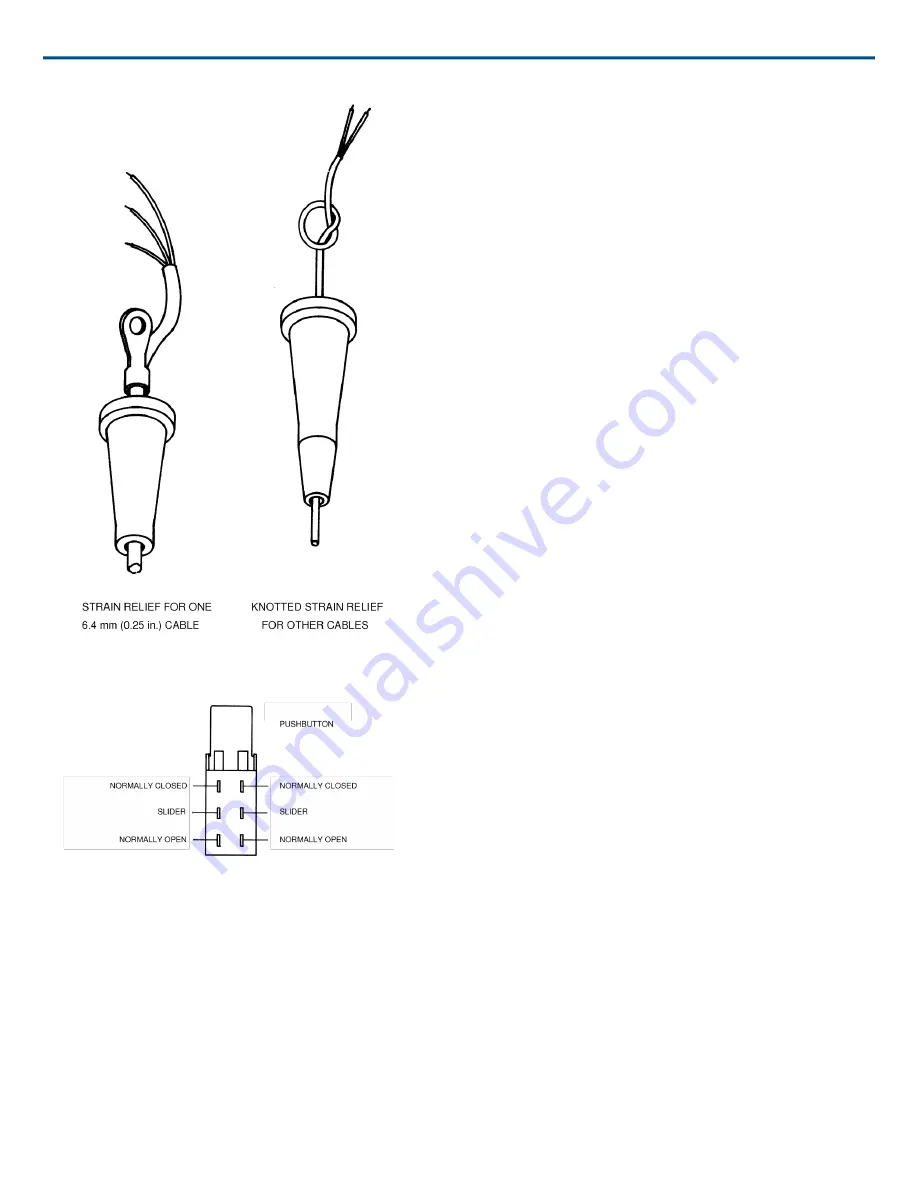
FIGURE 2:
FIGURE 3: TERMINAL SIDE OF SWITCH
Страница 1: ...eliable performance even in low current circuits The switch is a dou ble pole doublethrow type for maximum versatili ty Its push button combines with a rotary knob to provide either spring return momentary or lock ing action The unit is supplied with a crimp on strain relief tor 6 4mm 0 25 in diameter cable and with a flex relief for either large or small diameter cables The permanently attached b...
Страница 2: ...le above the flex relief to form a strain relief Leave enough raw cable above the knot to permit soldering the individual conductors to the switch terminals 3 Solder the conductors to the switch terminals to obtain the desired function see Figure 3 for switch configura tion Take care not to leave long bare conductors that may bridge across terminals and make unintended con nections When the switch...
Страница 3: ...vided thread forming screws to fasten the case back to the case front making sure not to pinch any leads If the strain relief is used make certain that it is captured by the screw through the lower cen ter back of the case FIGURE 1 FLEX RELIEF ...
Страница 4: ...Shure Incorporated 4 5 FIGURE 2 FIGURE 3 TERMINAL SIDE OF SWITCH ...
Страница 5: ...Shure Incorporated 5 5 FIGURE 4 ASSEMBLING THE SWITCH ...