


Bay Assembly (without radomes)
10
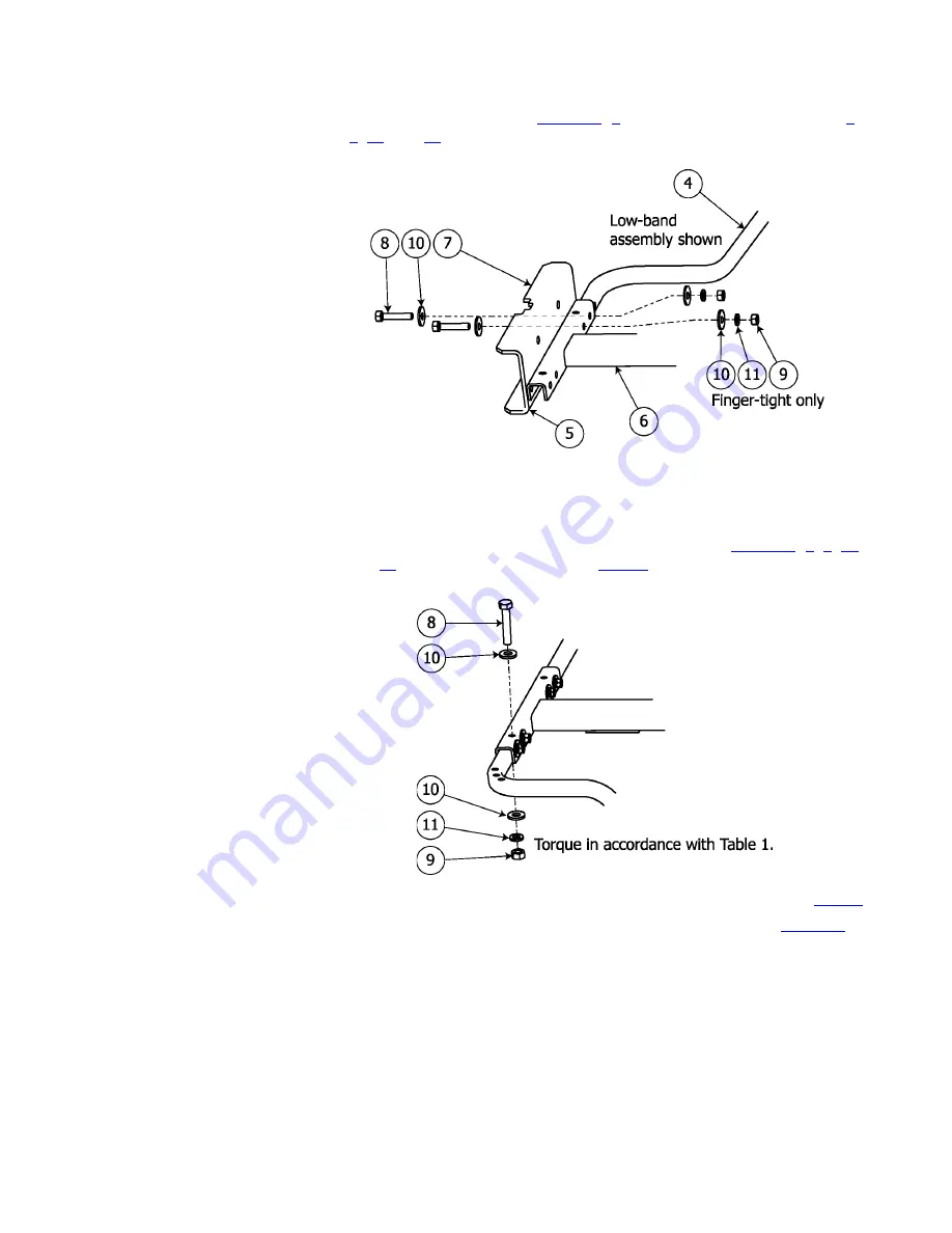
c. Attach the channel mount (
Figure 13
,
7
) and arms, using M8 hardware (
8
,
9
,
10
, and
11
), finger-tight only.
Figure 13. Channel attachment
CAUTION
To ensure proper arm alignment, always tighten the nuts on the vertical
bolts before tightening the horizontal ones.
d. Secure each arm with a vertical M8 bolt and hardware (
Figure 14
,
8
,
9
,
10
,
and
11
). Torque in accordance with
Table 1
on page 1.
Figure 14. Vertical bolts
e. Tighten the nuts on the horizontal bolts. Torque in accordance with
Table 1
.
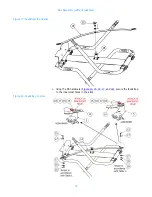
f. Repeat to attach the other two arms in their correct positions (
Figure 15
).
Содержание Versa2une SLV
Страница 4: ......
Страница 8: ......
Страница 11: ...3 Preparation Figure 2 Tower layout two bay antenna ...
Страница 12: ...Preparation 4 Figure 3 Tower layout four bay antenna ...
Страница 14: ......
Страница 34: ......
Страница 42: ......
Страница 44: ......
Страница 46: ......
Страница 50: ......