


11
Bay Assembly
2
Bay Assembly
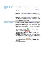
Attach the bay arms
(antennas without
de-icers).
[for single bay antennas and 1/2-wave-spaced antennas only]
a. Using 1/4-20 x 1-3/4" hardware (
, and
), attach the four
antenna arms (
) to the
innermost
pair of holes on the boom (
) mounting
stubs.
[for 2- to 8-bay full-wave-spaced antennas only]
b. Using 1/4-20 x 1-3/4" hardware (
,
), attach the four
antenna arms (
) to the
outermost
pair of holes on the boom (
) mounting
stubs.
c. Tighten the hardware before continuing.
Figure 9. Attaching the arms
Содержание 6842
Страница 4: ......
Страница 8: ......
Страница 11: ...3 Preparation Figure 1 Tower layout single bay antenna ...
Страница 12: ...Preparation 4 Figure 2 Tower layout two bay antenna ...
Страница 13: ...5 Preparation Figure 3 Tower layout three bay antenna ...
Страница 14: ...Preparation 6 Figure 4 Tower layout four bay antenna ...
Страница 15: ...7 Preparation Figure 5 Tower layout five bay antenna ...
Страница 16: ...Preparation 8 Figure 6 Tower layout six bay antenna ...
Страница 17: ...9 Preparation Figure 7 Tower layout eight bay antenna ...
Страница 18: ...Preparation 10 Figure 8 Top mounted installation ...
Страница 22: ......
Страница 26: ......
Страница 32: ......
Страница 37: ...29 Connecting the Antenna 2 bay Figure 17 Two way power divider mounted and connected ...
Страница 38: ......
Страница 46: ...Startup 38 Figure 21 Apply the signal ...
Страница 48: ......
Страница 51: ...43 Parts Figure 23 Endseal radome components ...
Страница 58: ......
Страница 59: ...51 Appendix A Selected Assembly Drawings The following are excerpts from selected assembly drawings ...
Страница 60: ...52 Figure A 1 22 Feed Strap with Endseal Radome Deicer ...
Страница 61: ...53 Figure A 2 6842 Exploded View with Endseal Radome ...
Страница 62: ...54 Figure A 3 Bay Arm Stickers ...
Страница 63: ...55 Figure A 4 Power Divider Mount Detail ...
Страница 64: ......