background image

Antenna Installation

6

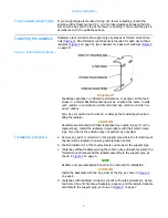
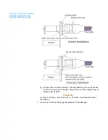
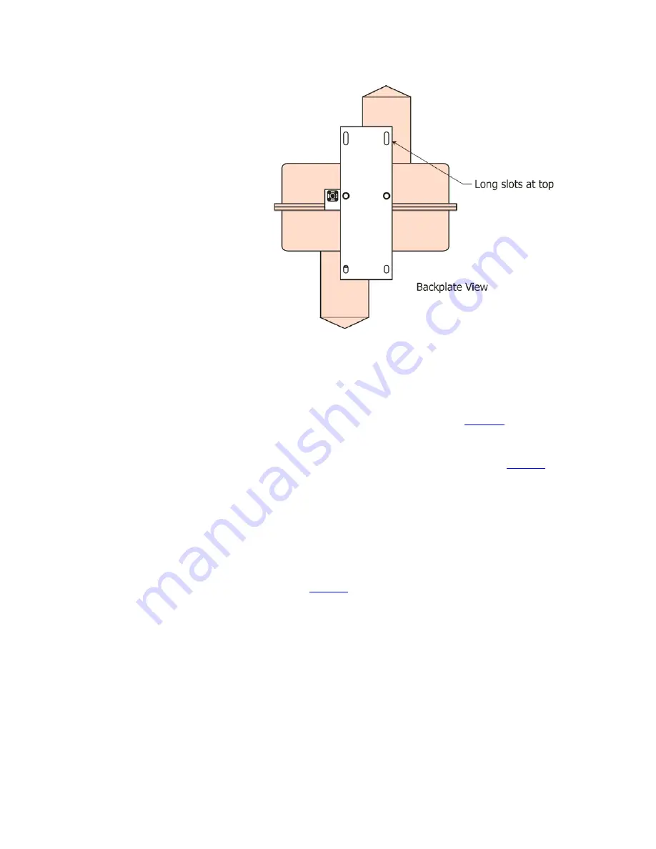
Figure 4. Radome backplate 

orientation

The design of the antenna requires that the interbay feedline be about 50% 

longer than the bay-to-bay spacing. To protect the slack cable from wind and 

vibration damage, it must be wrapped and secured to the support pipe.

CAUTION

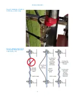
To  ensure  proper  antenna  performance,  the  excess  feedline  must  be 
wrapped  in  a  particular  fashion,  as  shown  in 

Figure  9

  on  page  9.  DO


NOT make a continuous spiral wrap around the pipe, as shown on the 

left. Doing so will ruin the VSWR of the antenna.

d. Wrap and secure the interbay feedline cable as follows (

Figure 9

):

CAUTION

Do not put too much tension on the feedline; just make it snug.
(1) Between each pair of antenna bays, loosen the connectors at both ends 

just  enough  to  allow  the  cable  to  swivel  as  it  is  wrapped.  This  will 

prevent kinking.

(2) Grasp the feedline in the middle and pull it gently out like a bowstring. 
(3) Then wrap the middle around the pipe, resulting in the “two-way spiral” 

shown in 

Figure 9

.

(4) Fasten the feedline to the pipe with plastic ties or electrical tape. Do not 

use metal ties, which can cut the line.

(5) Retighten the connectors at both ends.
(6) Repeat for each interbay section.

Содержание 6812DIN

Страница 1: ...Circularly Polarized FM Broadcast Antenna Model 6812DIN Instruction Manual Installation Operation Maintenance ...

Страница 2: ...omponents Our technical staff has a wealth of experience in the broadcast industry and is standing by to serve you in any way This manual is intended to give you a basic understanding of your antenna its proper and safe installation startup and operation and troubleshooting and maintenance information to keep it working satisfactorily for years to come Please have everyone involved with the antenn...

Страница 3: ...this manual in its entirety before beginning installation of your antenna Failure to follow the installation and operation instructions in this manual could lead to failure of your equipment and might even void your warranty ...

Страница 4: ......

Страница 5: ...me backplate orientation 6 Figure 5 Installation of radiator with radome exploded view 7 Figure 6 Installation of cable on top bay and bottom bay if center fed 8 Figure 7 Installation of cable on interior bay 8 Figure 8 Installation of cable on bottom bay end fed array 9 Figure 9 Wrapping and securing the interbay cables half wave spaced array only 9 Figure 10 Proper and improper application of sp...

Страница 6: ...ntents Chapter 5 Maintenance and Troubleshooting 19 Precautions 19 Maintenance log 19 Physical inspection 19 Paint 19 Radome removal and reinstallation 19 Return policy 20 Troubleshooting 20 Sample maintenance log 22 ...

Страница 7: ...k the parts to be sure that they will fit the support pipe Have a reliable tower person familiar with antennas and coaxial line inspect the tower and review the installation drawings before the full rigging crew arrives If design problems are found contact Shively Labs immediately Pay particular attention to Frequency of the antenna Freedom from interference by gussets leg flanges guy wires and th...

Страница 8: ...ce stray signals that will interfere with other services on the tower d To ensure good electrical contact between the antenna and the tower remove the paint and any rust at the support pipe and antenna mount locations before installing the antenna e After installing the antenna be sure to touch up the paint where you removed it Bolt tightening NOTE Use an anti seize compound to minimize galling on...

Страница 9: ...pipe installation Follow these guidelines a To ensure good electrical contact between the support pipe and the tower remove the tower paint and any rust at the support pipe mount locations before installing the mounts After installing the mounts be sure to touch up the paint where you removed it b Starting at the top of the support pipe mark the location of each bay in accordance with the installa...

Страница 10: ...reful not to disturb or damage the feed strap when han dling the radiator CAUTION Radiators are stenciled with their respective bay numbers bay 1 is the topmost bay Install the radiators in accordance with their match mark ings If you don t the antenna may not perform as expected Installation procedure a Remove any paint or corrosion on the support pipe where the formed mount channel will be locat...

Страница 11: ...onnector nuts finger tight only Using pliers or other mechanical means to tighten the connectors may damage them CAUTION The minimum bend radius of LMR 400 cable is 2 inches 50 8 mm a Locate the end of the harness that is marked Bay 1 Form the cable as shown in Figure 6 and attach that end to radiator 1 b The rest of the interbay cable harness should naturally fall into place Attach the tees on th...

Страница 12: ... Doing so will ruin the VSWR of the antenna d Wrap and secure the interbay feedline cable as follows Figure 9 CAUTION Do not put too much tension on the feedline just make it snug 1 Between each pair of antenna bays loosen the connectors at both ends just enough to allow the cable to swivel as it is wrapped This will prevent kinking 2 Grasp the feedline in the middle and pull it gently out like a ...

Страница 13: ...y of your antenna e Apply splicing tape as follows Figure 10 on page 10 1 Make sure the fittings and coax are clean and dry 2 Apply Scotch 130C Linerless Rubber Splicing Tape with the tacky side up 3 Stretch tape and apply half lapped to form a smooth void free splice Wrap tightly in and around the area where the connection is made Make sure the joint is fully covered but do not seal up against th...

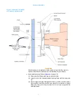
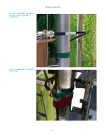
Страница 14: ...Antenna Installation 8 Figure 6 Installation of cable on top bay and bottom bay if center fed Figure 7 Installation of cable on interior bay ...

Страница 15: ...9 Antenna Installation Figure 8 Installation of cable on bottom bay end fed array Figure 9 Wrapping and securing the interbay cables half wave spaced array only ...

Страница 16: ...onnection carefully ensuring that the joint is fully sealed If more splicing tape is needed simply add it to the existing wrap It adheres well to itself CAUTION To prevent damage secure all coax to minimize wind induced motion and chafing f Tie all coax to the mounting pipe to prevent it from damage ...

Страница 17: ... electrical schematic Figure 11 on page 12 Electrical specifications Table 4 on page 13 Bay junction box Figure 12 on page 14 Thermostat readings Table 5 on page 15 Your system may also include specially ordered items such as a ground mounted main control box a power cable extending up the tower or a tower mounted dual setting thermostat Dual setting thermostat CAUTION Remember that conditions may...

Страница 18: ...nes NOTE A liquid tight conduit con nector 3 8 conduit size by 1 2 hub size for the harness entry to the tower junction box is packed loose with the de icer harness NOTE Shively recommends the use of shielded braided polyethylene covered wire or rubber sheathed flexi ble metal conduit or rigid conduit and weather tight fittings at all junctions ...

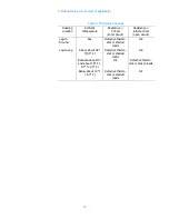
Страница 19: ...a tower junction box as shown schematically in 11 to connect the antenna s de icer harness to the main power c Using tie wraps secure the entire length of the de icer harness to the RF feedline at about 24 60 cm intervals Run the ten foot de icer pigtail along a feedline mount to the tower junction box and secure it to the mount and the tower Table 4 De Icer specifications Heater Leg Resistance He...

Страница 20: ... taking resistance readings Otherwise read ings may be affected by other components a Before you connect the thermostat measure the resistance across the thermostat circuit and from it to ground to ensure that there are no short circuits Thermostat readings should be as shown in Table 5 on page 15 b Mount the thermostat near the antenna and connect the thermostat leads to points S1 and S2 in the c...

Страница 21: ...rt circuit Resistance infinite ohms open circuit Leg to Ground Any Defective thermo stat or shorted leads OK Leg to Leg Above about 38 F 3 3 C Defective thermo stat or shorted leads OK Between about 10 and about 38 F 6 7 to 3 3 C OK Defective thermo stat or broken leads Below about 10 F 6 7 C Defective thermo stat or shorted leads OK ...

Страница 22: ......

Страница 23: ...lowing items have been done The antenna system has been installed in accordance with this manual and the installation drawing The de icer system if purchased has been checked out in accor dance with Chapter 3 All radiators are operating and VSWR is low System sweep data if desired have been recorded Check the system out as follows a Bring up RF power slowly and observe transmitter readings stabili...

Страница 24: ...e icer control system If you have the Shively Labs de icer control box and dual setting thermostat you have the choice of manual or automatic operation There are three switch settings AUTOMATIC OFF and MANUAL When the switch is set to AUTOMATIC the thermostat turns the heaters on and off according to the temperature When the switch is set to OFF the thermostat is overridden and the heaters will st...

Страница 25: ...spect radomes for cracks and plugged drain holes Re tighten all hardware hose clamps and U bolts to installation specifications Inspect hose clamps and U bolts carefully for signs of wear or fatigue caused by vibration or tower movement Paint The radiators should never be painted a coating of paint affects VSWR and they need no surface protection since they are made of copper and brass This includ...

Страница 26: ...s the impedance match between the transmitter and the antenna sys tem Possible causes include Wrong antenna for the application and frequency Occasionally incorrect frequency information is provided to Shively or an antenna designed for another application is used Defective cable connector in the cable harness Incorrect assembly of the antenna for example an upside down radiator radiators out of s...

Страница 27: ...g It is important to recognize however that apparent changes in coverage may be due to subjective factors or faults of the receiving equipment Before doing more than checking the VSWR be sure that an actual coverage change has occurred ...

Страница 28: ...eshooting 22 Sample maintenance log DATE DE ICER CURRENT or resistance VSWR OBSERVATIONS Visual Inspection of Antenna Obstruction Lighting Hard ware Checked Tower Repairs Accomplished etc BLACK b neut NEUT red bl RED r neut ...

Отзывы: