


7
RS-232 PROTOCOL COMMANDS ( RS-232 Control driver V2.0.1 )
The Shinybow switcher can be controlled via the RS-232 serial control port to
allow for interfacing to a PC, or similar third party control system.
The serial communication parameters are 9600 baud, 8 bit, No Parity and 1
stop bit - this is often referred to as 9600 8N1. When the unit recognizes a
complete command it will perform the requested action - there is no delimiter
character required.
The unit does not send out a message when a value is changed from the front panel or by IR control.
If the unit needs to be controlled via the front panel in addition to the RS-232 control, you should
regularly poll the unit status to ensure the control system accurately reflects the current settings.
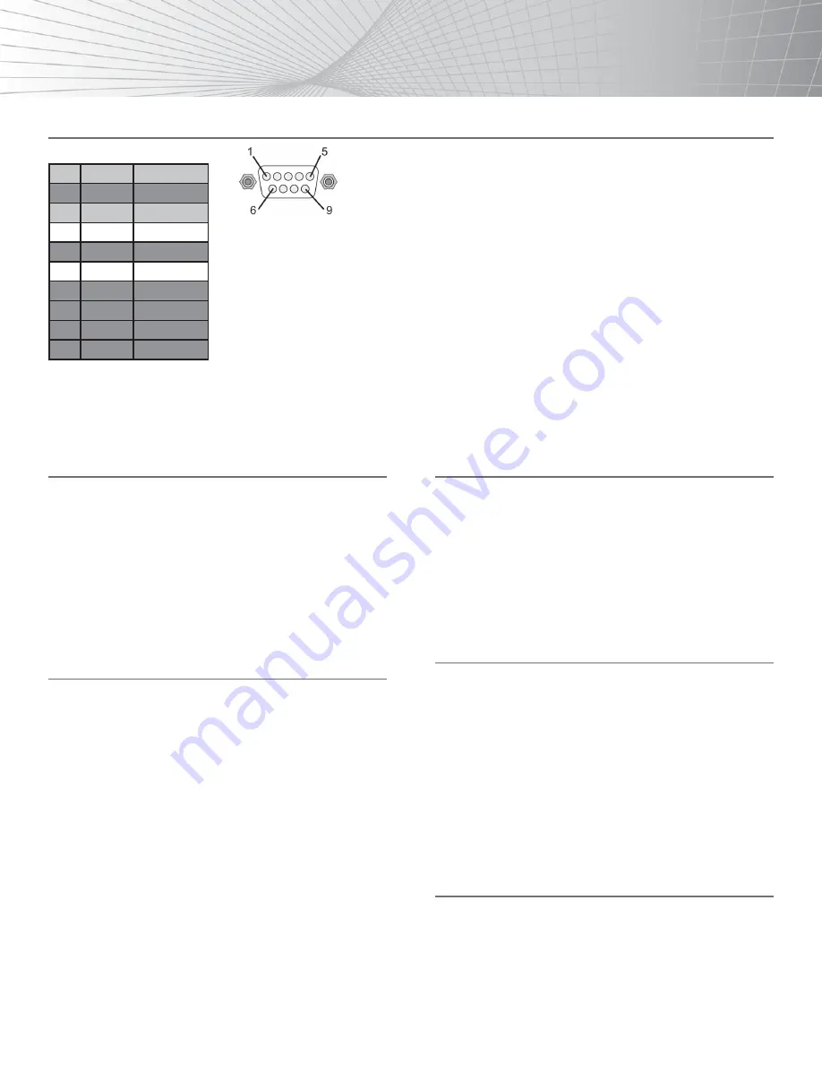
RS-232 SERIAL CONNECT
Pin RS-232
Definition
1
------
Not used
2
TX
Transmitter
3
RX
Receiver
4
------
Not used
5
GND
Ground
6
------
Not used
7
------
Not used
8
------
Not used
9
------
Not used
RS-232 SERIAL INTERFACE
COMMANDS
To Switch Inputs to Outputs
SBI0XO0Y
- Where X is Output Number (1-4) and Y is Input
Number (1-6)
Unit will respond with
SBUD0XOY
- Where X is Output Number (1-4) and Y is Input
Number (1-6)
Example:
Send Input 6 to Output 4
SBI06O04
- Send
SBUD06O4
- Rcvd
MORE STUFF FOR SB-5564
Note:
Turning the unit System Power Off over RS-232 will
extinguish the LED channel display leaving only the Power
switch LED on. The Video and Audio outputs will also mute.
While the unit is turned off by RS-232 it will continue to accept
and act upon switching commands. For example, if the unit is in
the off mode (via RS-232) and you send a command to switch
an input to an output, that route will complete and the video and
audio will now appear on that channel only. The front panel LED
channel display for that particular output will also show the input
selected (for that single output channel only). The remaining
LED’s will remain off and video and audio outputs muted. The
unit will still return status and change messages in response to
commands sent while in Power Off state. A hard reset command
(SBALLRST) will return the unit to normal operation and also
unlock the front panel.
POWER OFF MODE
SBSYSMOF
- Put system into Standby (Soft Power Off)
SBSYSMON
- Bring unit out of Standby (Soft Power On)
Unit will respond with
SBALOFAK
- Unit is in Standby
SBALONAK
- Unit is no longer in Standby
Example:
Put Unit in Standby (Soft Power)
SBSYSMOF
- Send
SBALOFAK
- Rcvd
FRONT PANEL LOCK
Note:
Hard resetting the unit will unlock the Front Panel controls.
SBSYSMLK
- When front panel is locked, changes can only
be
made by RS-232
SBSYSMUK
- Front Panel Unlock
Unit will respond with
SBSYSLOK
- Front Panel has been Locked
SBSYSULK
- Front Panel has been Unlocked
Example:
Lock Front Panel Buttons
SBSYSMLK
-Send
SBSYSLOK
-Rcvd
UNIT RESET
SBALLRST
- Reset every output to Input 1
Unit will respond with
SBRSTACK
- Unit has reset each Output to Input 1
Example:
Reset all outputs to Input 1
SBALLRST
- Send
SBRSTACK
- Rcvd


