


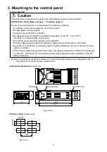


8
3.2mm
5
.8
m
m
o
r
le
ss
3.2mm
5
.8
m
m
or
le
ss
4.2 Lead wire solderless terminal
Use a solderless terminal with an insulation sleeve in which an M3 screw fits as shown below.
The torque should be 0.63N•m.
Solderless
terminal
Manufacturer
Model
Torque
Nichifu Terminal Industries CO.,LTD.
TMEV1.25Y-3
Y type
Japan Solderless Terminal MFG CO.,LTD.
VD1.25-B3A
Nichifu Terminal Industries CO.,LTD.
TMEV1.25-3
Round type
Japan Solderless Terminal MFG CO.,LTD.
V1.25-3
0.63N•m
(Fig. 4.2-1)
4.3 Heater burnout alarm option
(1)
This alarm is not usable for detecting heater current
under phase control.
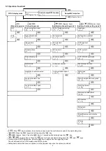
(2) Use the current transformer (CT) provided, and pass one
lead wire of the heater circuit into the hole of the CT.
(3) When wiring, keep the CT wire away from AC sources
or load wires to avoid the external interference.
(Fig. 4.3-1)
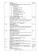
5. Setup
The PV/SV display indicates the characters of the sensor type and temperature unit
/
for approx.
2 seconds after power-on. During this time, all outputs and the LED indicators are in OFF status.
Refer to (Table 5-1) and (Table 5-2).
Control will then start indicating the PV (process variable) or SV (desired value) on the PV/SV display.
If PV display is selected during PV/SV display switching, the PV (process variable) will be indicated.
If SV display is selected, the SV (desired value) will be indicated.
(Table 5-1)
(Table 5-2)
PV/SV display
PV/SV display
Input
TC K input
K
J
K 0 to 400
0 to 750
PL-
N
K 0.0 to 400.0
0.0 to 750.0
E
Pt100 (With decimal point)
JPt100 (With decimal point)
Pt100
JPt100
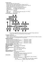
CT input Terminals
Power
supply
Heater
CT
(8)
(9)