

- 3 -
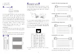
1000Base SFP fiber port(mini-GBIC)
1000Base SFP fiber port adopts gigabit mini-GBIC transmission,
can choice different SFP module according to different transfer
distance. Fiber interface must use for pair, TX port is transmit side,
must connect to RX (receive side). The fiber interface support loss
line indicator.
Suppose
: If you make your own cable, we suggest labeling the
two sides of the same line with the same letter (A-to-A and
B-to-B, shown as below, or A1-to-A2 and B1-to-B2).
【
LED Indicator
】
LED indictor light on the front panel of product, the function of
each LED is described in the table as below.
System indication LED
LED
State
Description
P1
ON
Power is being supplied to power
input PWR1
OFF
Power is
not
being supplied to
power input PWR1
P2
ON
Power is being supplied to power
input PWR2
OFF
Power is
not
being supplied to
power input PWR2
Alarm
ON
When the alarm is enabled, which
any one way power supply fault
OFF
Power supply normal, the alarm is
disabled.
Run
ON/OFF
System is not running well
Blinking
System is running well
Link/ACT
(G1~G20)
ON
Port connection is active
Blinking
Data transmitted
OFF
Port connection is not active
【
Installation
】
Before installation, confirm that the work environment meet the
installation require, including the power needs and abundant
space. Whether it is close to the connection equipment and other
equipments are prepared or not.
1. Avoid in the sunshine, keep away from the heat fountainhead or
the area where in intense EMI.
2. Examine the cables and plugs that installation requirements.
3. Examine whether the cables be seemly or not (less than 100m)
according to reasonable scheme.
4. Power: support 12 ~ 48VDC power supply
5. Environment: working temperature: -40
~
75
℃
Storage Temperature: -40
~
85
℃
Relative humidity 5%
~
95%
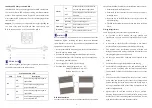
DIN Rail Installation
In order to use in industrial environments expediently, the product
adopt 35mm DIN-Rail installation, the installation steps as below:
1.
Examine the DIN-Rail attachment
2.
Examine DIN Rail whether be firm and the position is
suitability or not.
3.
Insert the top of the DIN-Rail into the slot just below the
stiff metal spring.
4.
The DIN-Rail attachment unit will snap into place as shown
below.
Wiring Requirements
Cable laying need to meet the following requirements,
1.
It is needed to check whether the type, quantity and
specification of cable match the requirement before cable
laying;
2.
It is needed to check the cable is damaged or not, factory
records and quality assurance booklet before cable laying;
3.
The required cable specification, quantity, direction and
laying position need to match construction requirements, and
cable length depends on actual position;
4.
All the cable cannot have break-down and terminal in the
middle;
5.
Cables should be straight in the hallways and turning;
6.
Cable should be straight in the groove, and cannot beyond the
groove in case of holding back the inlet and outlet holes.
Cables should be banded and fixed when they are out of the
groove;
7.
User cable should be separated from the power lines. Cables,
power lines and grounding lines cannot be overlapped and
mixed when they are in the same groove road. When cable is
too long, it cannot hold down other cable, but structure in the
middle of alignment rack;
8.
Pigtail cannot be tied and swerved as less as possible.
Swerving radius cannot be too small (small swerving causes
terrible loss of link). Its banding should be moderate, not too
tight, and should be separated from other cables;


