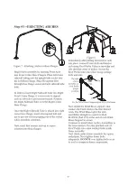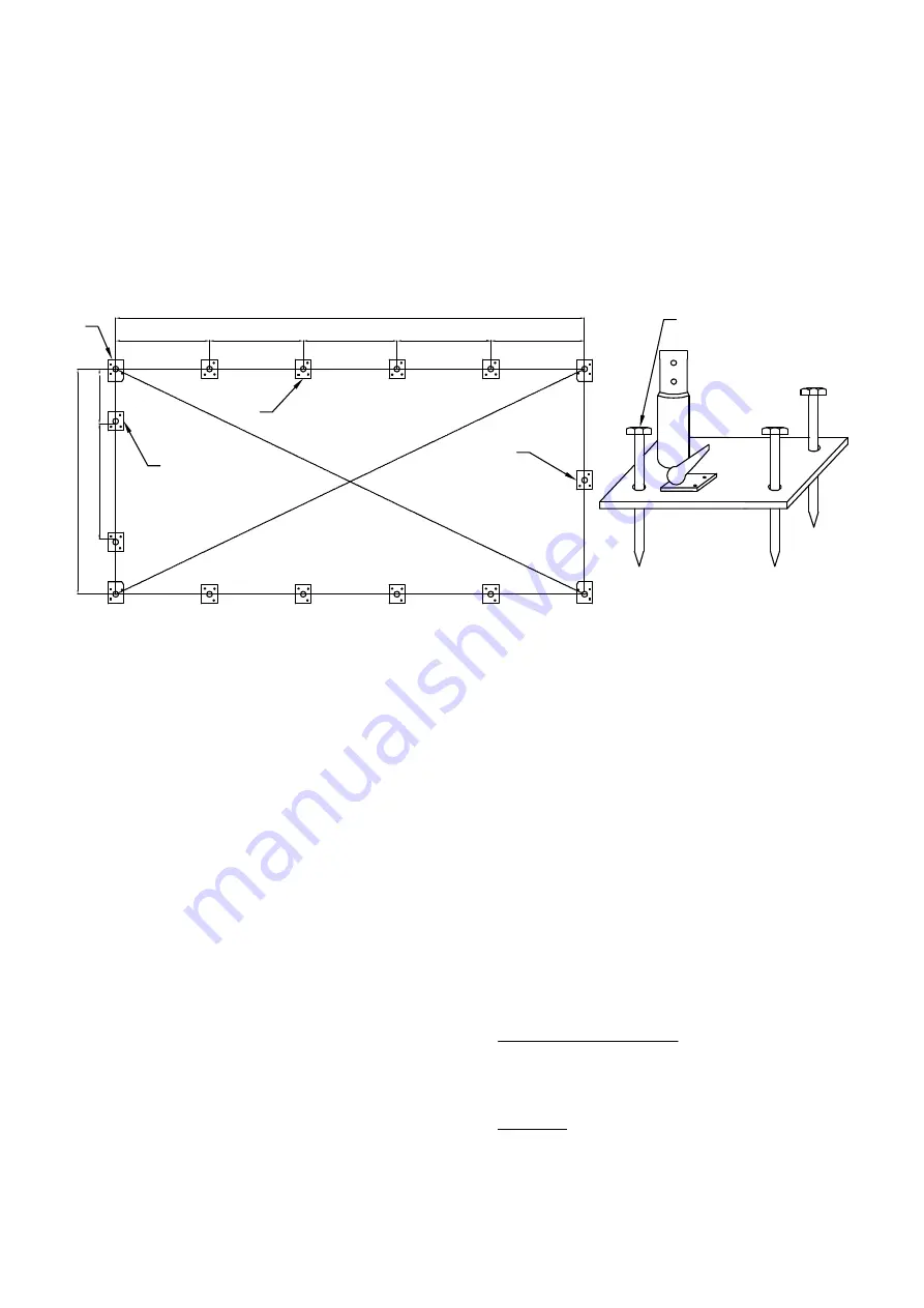
Figure 3
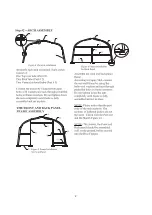
As Figure 3 shows, each
base flange is equipped
with three stake pegs.
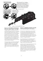
Begin by determining exact
location of the four (4) corners of
the building. Mark front edge and
side-to-side width of assembly on
ground. Drive alignment stakes into
the ground outside of the markings,
and draw alignment strings along
both ends and sides of the building
to the dimensions shown in Figure
2. The outline of the strings will
represent the final location of the
base flanges. The initial location of
each Corner Base Flanges is critical
to the alignment and fit of the frame
components and cover.
Step #1 --SECURING BASE FLANGES
Sit the building boxes in the chosen location. Remove all the components
from packaging to ensure all components are present by checking with the
Part List.
Locate the Left Corner Base Flange
and Right Corner Base Flange(part
#5). Secure the base flanges with
Stake Pegs (Part #40).
Measurements shown in Figure 2
are to the center of the upright
sockets on each Base Flange.
The Shelter must be secured to a
firm surface that can receive and
retain stake pegs firmly in position.
The shelter should be installed on
FIRM GROUND, not on SWAMP,
SOFT/WET GROUND. The Base
Flanges must be secured so they
cannot be moved. Arches are
tensioned at their base as they
insert into the Base Plate sockets.
40
6
10.0m
2.0m
2.0m
8
7
5
0
.5
m
3
m
4
.0
m
2.0m
2.0m
2.0m
Figure 2 Position of Base Flanges
F
R
O
N
T
Diagonals are equal
Содержание JIT-1333M
Страница 1: ...MODEL JIT 1333M www vikre no ...
Страница 2: ...1 ...
Страница 3: ...2 ...
Страница 4: ...3 Part List of Model JIT 1333M L10 0xW4 0xH3 7m ...
Страница 5: ...4 ...
Страница 7: ...6 ...
Страница 8: ...7 ...
Страница 9: ...8 ...
Страница 11: ...10 ...
Страница 12: ...11 ...
Страница 13: ...12 ...


