background image

E-19

Setup & Connections

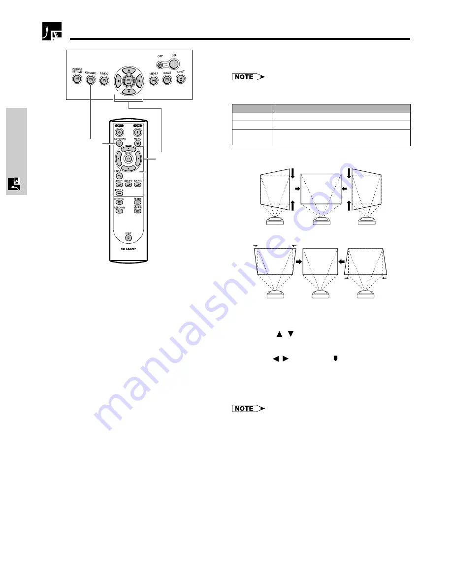
Keystone Correction

This function can be used to adjust the Keystone
settings.

• For details about using the menu screen, see page 26.

Description of 2D Keystone Correction

Selected item

Description

H Keystone

Horizontally adjusts the keystone settings.

V Keystone

Vertically adjusts the keystone settings.

Reset

V and H Keystone adjustments are returned to the factory
preset settings.

Horizontal Keystone Correction

Vertical Keystone Correction

1

Press 

KEYSTONE

 on the projector or on the

remote control.

2

Press 

/

 to select “H Keystone” or “V

Keystone”.

3

Press 

/

 to move the   mark on the selected

adjustment item to the desired setting.

4

To return to the normal screen, press 

KEYSTONE

again.

• Straight lines and the edges of the displayed image may

appear jagged, when adjusting the Keystone setting.

• When adjusting “H Keystone” and “V Keystone” at the same

time, the values of adjustable angles for each setting
become smaller.

• The “Digital Shift” and “Subtitle” cannot be adjusted when

Keystone correction is applied.

2

3

1

4

Содержание XV-Z90U

Страница 1: ...OPERATION MANUAL MODE D EMPLOI MANUAL DE OPERACION MANUAL DE OPERAÇÃO XV Z90U PROJECTOR PROJECTEUR PROYECTOR PROJETOR ENGLISH FRANÇAIS ESPAÑOL PORTUGUÊS ...

Страница 2: ... directly into the beam of light WARNING To reduce the risk of fire or electric shock do not expose this product to rain or moisture WARNING FCC Regulations state that any unauthorized changes or modifications to this equipment not expressly approved by the manufacturer could void the user s authority to operate this equip ment CAUTION TO REDUCE THE RISK OF ELECTRIC SHOCK DO NOT REMOVE COVER NO US...

Страница 3: ...he following conditions 1 This device may not cause harmful interference and 2 this device must accept any interference received including interference that may cause undesired operation Responsible Party SHARP ELECTRONICS CORPORATION Sharp Plaza Mahwah New Jersey 07430 TEL 1 800 BE SHARP 1 800 237 4277 INFORMATION This equipment has been tested and found to comply with the limits for a Class B di...

Страница 4: ... equipped with a three wire grounding type plug a plug having a third grounding pin This plug will only fit into a grounding type power outlet This is a safety feature If you are unable to insert the plug into the outlet contact your electrician to replace your obsolete outlet Do not defeat the safety purpose of the grounding type plug 13 Power Cord Protection Power supply cords should be routed s...

Страница 5: ...ruction If the cooling fan becomes obstructed a protection device will automatically turn off the projector lamp This does not indicate a malfunction Remove the projector power cord from the wall outlet and wait at least 10 minutes Then turn on the power by plugging the power cord back in This will return the projector to the normal operating condition This caution is found at the bottom of the pr...

Страница 6: ...p has been used for 2 400 hours LAMP and will blink in the lower left corner of the picture to advise you to replace the lamp See page 46 for lamp replacement If the lamp has been used for 2 500 hours the projector power will automatically turn off and the projector will enter standby mode Refer to Lamp Maintenance Indicators on page 44 for details Using the Terminal Cover When the projector is us...

Страница 7: ...6 Basic Operations 26 Menu Bars 27 Adjusting the Picture 29 Adjusting the Computer and DVD DTV Images 33 Lamp Maintenance Indicators 44 Lamp Maintenance 45 Confirming the Lamp Usage Time 45 Replacing the Lamp 46 Cleaning the Ventilative Holes 49 Using the Kensington Lock 50 Troubleshooting 50 For SHARP Assistance U S A only 50 Connecting Pin Assignments 51 RS 232C Specifications and Command Settin...

Страница 8: ...ly corrects the size of projected images The function enables diagonal projection and the wider range settings 7 HDCP High bandwidth Digital Content Protection System Digital entertainment content is protected from copying with the HDCP system 8 For Use with DTV Allows projection of DTV images and 16 9 wide screen images when connected to a DTV decoder or similar video system 9 Easy to use Graphic...

Страница 9: ...lative hole LAMP REPLACEMENT indicator TEMPERATURE WARNING indicator 19 ADJUSTMENT buttons ƒ ß 26 UNDO button 26 MENU button 24 RESIZE button 24 INPUT button 17 Swivel Stand LOCK UNLOCK lever 15 Remote control sensor 9 Lens cap Zoom knob 16 Exhaust ventilative hole 4 Focus ring 16 18 Lens shift dial 26 ENTER button 19 KEYSTONE button POWER buttons ON OFF 16 32 PICTURE SETTING button Side and Rear ...

Страница 10: ... socket Intake ventilative hole 49 13 INPUT 2 DVI digital port INPUT 1 COMPONENT terminals RCA INPUT 4 VIDEO terminal RCA DIGITAL INPUT TYPE switch 13 INPUT 3 S VIDEO terminal 4 pin Mini DIN 14 RS 232C port 9 pin D sub 15 Remote control sensor 12 Attaching the Lens Cap After putting the lens cap strap on the lens cap pass the other end of the strap through the hole under the projector next to the ...

Страница 11: ...ery cover into the opening and press the cover until it clicks in place Top View Remote Control LIGHT button 16 24 35 36 19 26 26 26 24 24 24 24 24 32 15 POWER buttons ON OFF ENTER button 19 KEYSTONE button UNDO button INPUT 1 button INPUT 2 button INPUT 4 button AUTO SYNC button RESIZE button PICTURE SETTING button MENU button ADJUSTMENT buttons ƒ ß INPUT 3 button DIGITAL INPUT button RGB COMP bu...

Страница 12: ...ccessories Power cord QACCDA007WJPZ Remote control RRMCGA064WJSA Two AA size batteries Terminal cover GCOVAA116WJKA Operation manual TINS A286WJZZA Lens cap CCAPHA004WJ01 Lens cap strap UBNDT0013CEZZ Screws for terminal cover XBBSN40P10000 ...

Страница 13: ...ut or Video output terminal of the video source The S video input terminal uses a video signal system where the picture is separated into a color and luminance signal to realize a higher quality image For higher quality video you may use the S video input terminal on the projector An S video cable is commercially available If your video equipment does not have an S video output terminal use the co...

Страница 14: ...nd connecting S video cable commercially available Video cable commercially available Projector Connecting to a DVD player and DTV decorder with Component output for INPUT 1 Connecting to a DVD player and DTV decoder with component output for INPUT 2 1 Connect the 3 RCA to 15 pin D Sub cable using the DVI to 15 pin D Sub adaptor 2 Use the above cables to connect the projector and the DTV decoder W...

Страница 15: ... to 15 pin D Sub adaptor 2 Use the above cables to connect the projector and the DTV decoder When connecting this projector to analog RGB output of the DTV decoder select Component for Signal Type on the OSD menu or press RGB COMP on the remote control See page 36 CAUTION Make sure to turn both the projector and the video equipment off before switching the DIGITAL INPUT TYPE swich and connecting D...

Страница 16: ...onding terminal on a computer Make sure to turn both the projector and the video equipment off before switching the DIGITAL INPUT TYPE swich and connecting Connect an RS 232C cable null modem cross type commercially available to the serial port on the computer CAUTION Do not connect or disconnect an RS 232C cable to or from the computer while it is on This may damage your computer Refer to Compute...

Страница 17: ...ssage Terminating Please wait will appear If you accidentally pressed POWER OFF and do not want to turn off the power wait until the confirmation message disappears When POWER OFF is pressed twice the POWER indicator will illuminate in red and the cooling fan will run for about 90 seconds The projector will then enter standby mode Wait until the cooling fan stops running before disconnecting the p...

Страница 18: ...ght or direction of the projector is adjusted the image may become distorted keystoned depending on the relative positions of the projector and the screen See page 19 for details on the keystone correction 1 2 3 Removing the Swivel Stand Lift the projector 2 with pressing the removing stand button on the back of the projector 1 Attaching the Swivel Stand Align the tabs on the front bottom of the p...

Страница 19: ...ns DOWN UP Lens shift dial UP DOWN The picture can be adjusted within the shift range of the lens by rotating the lens shift dial on the top of the projector using your finger Using the Lens Shift Projector Projected Image ...

Страница 20: ...tal Keystone Correction Vertical Keystone Correction 1 Press KEYSTONE on the projector or on the remote control 2 Press to select H Keystone or V Keystone 3 Press to move the mark on the selected adjustment item to the desired setting 4 To return to the normal screen press KEYSTONE again Straight lines and the edges of the displayed image may appear jagged when adjusting the Keystone setting When ...

Страница 21: ...to the screen See page 17 3Align the edge of the screen closest to the projector with the test pattern by adjusting the zoom and the Swivel Stand See pages 16 and 17 4Adjust the Keystone function so that the size of the projected image matches the screen size See page 19 5Align the image on the screen by adjusting the zoom function and the Swivel Stand 6Adjust the focus so that the projected image...

Страница 22: ...8 m 1 8 0 5 m Projection distance b 33 9 10 3 m 25 4 7 7 m 16 10 5 1 m 14 1 4 3 m 12 1 3 7 m 10 2 3 1 m 6 8 2 0 m Composite S video 480i P 1080i 14 1 4 3 m 10 6 3 2 m 6 11 2 1 m 5 11 1 8 m 4 11 1 5 m 3 11 1 2 m 2 7 0 8 m 720P 10 2 3 1 m 7 7 2 3m 4 11 1 5m 4 3 1 3 m 3 7 1 1m 2 11 0 9 m 1 12 0 6 m RGB 8 6 2 6 m 6 3 1 9 m 4 3 1 3 m 3 3 1 0 m 2 11 0 9 m 2 4 0 7 m 1 8 0 5 m Vertical placement range f 7...

Страница 23: ...he screen with all feet flat and level Tilting or angling the projector will reduce the effectiveness of the lens shift function Screen size 100 inches 254 cm Aspect ratio 4 3 90 90 Screen Upper and Lower Lens Shift Position Ceiling Mount When the projector is in the inverted position use the upper edge of the screen as the base line and exchange the lower and upper lens shift values Screen Upper ...

Страница 24: ... the translucent screen CAUTION When using a mirror be sure to carefully position both the projector and the mirror so the light does not shine into the eyes of the audience It is recommended that you use the optional Sharp ceiling mount bracket for this installation Before mounting the projector remove the Swivel Stand See page 17 for removing and attaching the Swivel Stand Before mounting the pr...

Страница 25: ...l that the projector is not preset to receive is received NOT REG will be displayed On screen Display Adjusting the Picture Aspect Ratio This function allows you to modify or customize the picture display mode to enhance the input image Depending on the input signal you can choose NORMAL BORDER or STRETCH image 1 Press RESIZE Each time RESIZE is pressed the picture mode changes as shown on the nex...

Страница 26: ...rea on which the image is not included in the original signals Projects the image fully on a screen while maintaining the aspect ratio Projects the image on the screen whose surrounding areas are cut out to make a 4 3 screen while maintaining the aspect ratio Projects the image on the screen whose upper and lower areas are cut out to make a 16 9 screen while the image is horizontally enlarged Mode...

Страница 27: ...t a specific adjustment item 4 Press ENTER after selecting the item if you want to display a single adjustment item Only the selected adjustment item will appear 5 Press to adjust the item 6 Press UNDO to return to the previous screen 7 To exit the menu screen press MENU For details on items on the menu screen see the tree charts on pages 27 and 28 This projector has two sets of menu screens that ...

Страница 28: ...Menu Position Menu Color Opaque Translucent Center Lamp Timer OSD Display ON OFF Signal Type Upper Right Lower Right Upper Left Lower Left Subtitle Ⳮ10 ⳮ10 PRJ Mode Items on the INPUT 1 or 2 Mode Menu Bar The Digital Shift and Subtitle cannot be adjusted when Keystone correction is applied The resolution vertical frequency and horizontal frequency figures displayed above are for example purposes o...

Страница 29: ...ressive Brighten Background Options PAL NTSC3 58 NTSC4 43 PAL M PAL 60 SECAM Language English Deutsch Español Nederlands Français Italiano Svenska Português Blue None Auto Power Off ON OFF Menu Position Menu Color Opaque Translucent Center PRJ Mode Front FrontⳭCeiling Rear RearⳭCeiling 7500k CLR Temp Gamma White Emphasis ON OFF Picture Setting 3D Progressive Memory 1 Lamp Timer OSD Display ON OFF ...

Страница 30: ...set in Picture All image adjustment items are returned to the factory preset settings Contrast Brightness Color Tint Sharp Red Blue CLR Temp Gamma White Emphasis Picture Setting Reset On screen Display e g VIDEO input in INPUT 3 or 4 mode 1 2 Color Tint and Sharp do not appear for RGB input in INPUT 2 mode For details on Gamma see Gamma Correction Function on page 31 For details on CLR Temp see Ad...

Страница 31: ...screen press MENU Values on CLR Temp are only for general standard purposes The less the value is set to the warmer reddish incandescent like the image becomes The more the value is set to the cooler bluish fluorescent like the image becomes CLR Temp cannot be used in the DIGITAL INPUT mode On screen Display 2 3 4 1 5 Emphasizing the Contrast This function emphasizes the bright portions of images ...

Страница 32: ...s for a more exciting theater experience Emphasizes the gradation of the intermediate to high brightness portions of the image for more detailed expression Brighten the darker portions of images for easier viewing in a dimly lit room 1 Press MENU The Picture menu screen appears 2 Press to select Gamma and then press 3 Press to select the desired gamma mode 4 Press ENTER to save the setting 5 To ex...

Страница 33: ...ted in any input modes Memory Besides Memory 1 to Memory 5 other settings OFF can be stored for each input mode Memory OFF can be selected for each input mode Selecting Memory 1 5 or Memory OFF Using the PICTURE SETTING Button 1 Press PICTURE SETTING Each time PICTURE SETTING is pressed the memory number changes as shown below Memory 1 Memory 2 Memory 3 Memory OFF Memory 5 Memory 4 Storing the Adj...

Страница 34: ...lay the Fine Sync menu screen 3 Press to select a specific adjustment item 4 Press to move the mark of the selected adjustment item to the desired setting 5 To exit the menu screen press MENU To reset all adjustment items select Reset on the Fine Sync menu screen and press ENTER The adjustable area of each item may be changed according to the input signal On screen Display Adjusts vertical noise A...

Страница 35: ...e setting 6 To exit the menu screen press MENU Avoid displaying computer patterns which repeat every other line horizontal stripes Flickering may occur making the image hard to see When inputting DTV 1080i signal select the corresponding type of signal in step 4 above When inputting 720P RGB signal select the corresponding type of signal in step 4 above Special modes cannot be used in the DIGITAL ...

Страница 36: ...enu screen appears 2 Press to display the Fine Sync menu screen 3 Press to select Auto Sync 4 Press to select ON or OFF 5 To exit the menu screen press MENU When the optimum image cannot be achieved with Auto Sync adjustment use manual adjustments See page 33 The Auto Sync adjustment may take some time to complete depending on the image of the computer connected to the projector Auto Sync cannot b...

Страница 37: ...elected item ON OFF Description of OSD Display All On screen Display are displayed INPUT is not displayed 2 3 4 1 5 2 3 4 1 5 On screen Display This function allows you to select the input signal type Component or RGB for INPUT 2 1 Press MENU The Picture menu screen appears 2 Press to display the Options menu screen 3 Press to select Signal Type and then press 4 Press to select RGB or Component 5 ...

Страница 38: ...input system mode is preset to Auto however it can be changed to a specific system mode if the selected system mode is not compatible with the connected audiovisual equipment 1 Press MENU The Picture menu screen appears 2 Press to display the Options menu screen 3 Press to select Video Systems and then press 4 Press to select the desired video system mode 5 Press ENTER to save the setting 6 To exi...

Страница 39: ...u screen appears 2 Press to display the Options menu screen 3 Press to select Digital Shift 4 Press to move the mark of the Digital Shift setting 5 To exit the menu screen press MENU The Digital Shift cannot be adjusted when Keystone correction is applied 2 3 4 1 5 Digital Shift Subtitle Reset Adjusts the vertical position of the image Adjusts the vertical size of the image Digital Shift and Subti...

Страница 40: ...hanged to a certain point The subtitle setting can be adjusted more effectively with the Digital Shift function The Subtitle cannot be adjusted when Keystone correction is applied Adjustments for the Screen Position and Size On screen Display 2 3 4 1 5 Subtitle Setting With this function you can adjust the vertical size of the display to allow for subtitles Description of Subtitle Setting The imag...

Страница 41: ... The menu is displayed on the upper right of the image The menu is displayed on the lower right of the image The menu is displayed on the upper left of the image The menu is displayed on the lower left of the image Description Selected item 2 3 4 1 5 Selecting the Menu Color This function allows you to select the color of the menu screen Description of Menu color 1 Press MENU The Picture menu scre...

Страница 42: ... off 1 Press MENU The Picture menu screen appears 2 Press to display the Options menu screen 3 Press to select Auto Power Off 4 Press to select or 5 To exit the menu screen press MENU Auto Power Off is factory preset to When the Auto Power Off function is set to On 5 minutes before the power turns off the message Power OFF in X min will appear on the screen to indicate the remaining minutes Power ...

Страница 43: ...etups See page 23 for these setups On screen Display 2 3 1 5 4 Selecting the On screen Display Language English is the preset language for the On screen Display however this can be changed to German Spanish Dutch French Italian Swedish Portuguese Chinese Korean or Japanese 1 Press MENU The Picture menu screen appears 2 Press to display the Language menu screen 3 Press to select the desired languag...

Страница 44: ...y R Contrast G Contrast B Contrast R Brightness G Brightness B Brightness Reset For less contrast of red color For less contrast of green color For less contrast of blue color For less brightness of red color For less brightness of green color For less brightness of blue color button button For more contrast of red color For more contrast of green color For more contrast of blue color For more bri...

Страница 45: ...re are two types of warning lights a TEMPERATURE WARNING indicator that warns you when the projector is too hot and a LAMP REPLACEMENT indicator that warns you when to change the lamp If a problem occurs either the TEMPERATURE WARNING indicator or the LAMP REPLACEMENT indicator will illuminate in red After turning off the power follow the procedures given below If the TEMPERATURE WARNING indicator...

Страница 46: ... lamp usage time will be displayed in Lamp Timer 3 To exit the menu screen press MENU It is recommended that the lamp be replaced after approximately 2 400 cumulative hours of use See page 46 for lamp replacement On screen Display Problem Lamp has been used for over 2 400 hours Lamp has been used for over 2 500 hours Possible Solution Purchase a replacement lamp unit lamp cage module of the curren...

Страница 47: ...placed at your nearest Authorized SharpVision Service Center IMPORTANT NOTETO U S CUSTOMERS The lamp included with this projector is backed by a 90 day parts and labor limited warranty All service of this projector under warranty including lamp replacement must be obtained through an Authorized SharpVision Service Center or Dealer For the name of the nearest Authorized SharpVision Service Center o...

Страница 48: ...g the lamp unit CAUTION Turn off the power Unplug the power cord 4 6 Loosen the user service screw that secures the lamp cage cover 5 Slide the lamp cage cover in the direction of the arrow 1 3 Turn off the power 2 Unplug the power cord Remove the Swivel Stand See page 17 Loosen and remove the three securing screws from the lamp cage Press POWER OFF Wait until the cooling fan stops running 7 Remov...

Страница 49: ...onfirm it is reset on the Lamp Timer menu Replacing the Lamp 11 10 Attach the lamp unit cover Tighten the user service screw to fasten the lamp cage cover Press POWER ON on the projector to reset the lamp timer Press and in order Then press Plug the power cord 12 13 LAMP 0000H is displayed on the screen ...

Страница 50: ...should be cleaned every 100 hours of use Clean the ventilative holes more often when the projector is used in a dirty or smoky location How to clean the ventilative holes Side and Rear view Cleaning the Ventilative Holes Clean the dust off by putting the cleaner hose on the intake ventilative holes Cleaning 2 Unplug the power cord 1 Bottom view Intake ventilative holes Intake ventilative holes Cle...

Страница 51: ...ange the input signal type See page 36 For SHARP Assistance U S A only If you encounter any problems during setup or operation of this projector first refer to the Troubleshooting section on this page If this operation manual does not answer your question please call toll free 1 877 DTV SHARP 1 877 388 7427 for further assistance Or send us an e mail at lcdsupport sharpsec com Our World Wide Web a...

Страница 52: ...ted C3 Not connected 13 Not connected C4 Not connected 14 5V power C5 Ground 15 Ground DVI Analog RGB Input Pin No Signal Pin No Signal 1 Not connected 16 Hot plug detection 2 Not connected 17 Not connected 3 Not connected 18 Not connected 4 Not connected 19 Not connected 5 Not connected 20 Not connected 6 DDC clock 21 Not connected 7 DDC data 22 Not connected 8 Vertical sync 23 Not connected 9 No...

Страница 53: ...he projector processes the command from the computer it sends a response code to the computer Return code 0DH C1 C2 C3 C4 P1 P2 P3 P4 Response code format Normal response O K Return code 0DH Problem response communication error or incorrect command E R R Return code 0DH Command 4 digits Parameter 4 digits Command format When more than one code is being sent send each command only after the OK resp...

Страница 54: ...POWER ON POWER OFF INPUT 1 COMPONENT 1 INPUT 2 COMPONENT 2 INPUT 3 S VIDEO INPUT 4 VIDEO DIGITAL MODE OK OR ERR OK OR ERR OK OR ERR OK OR ERR OK OR ERR OK OR ERR OK OR ERR P P I I I I I O O V V V V V W W E E E E E R R D D D D D _ _ _ _ _ _ _ _ _ _ _ _ _ _ _ _ _ _ _ _ _ 1 0 1 2 3 4 5 BUTTONS REMOTE CONTROL BUTTONS COMMAND PARAMETER RETURN ...

Страница 55: ...change display modes can be found in your notebook computer s operation manual PC MAC WS Horizontal Frequency kHz Vertical Frequency Hz VGA PC SVGA XGA VESA Standard DVI Support Resolution 640 350 720 350 640 400 720 400 640 480 800 600 1 024 768 Display Upscale Intelligent Compression True 27 0 60 27 0 60 27 0 60 60 31 5 70 31 5 70 31 5 70 31 5 60 34 7 70 37 9 72 37 5 75 31 4 50 35 1 56 37 9 60 4...

Страница 56: ...E 55 Appendix 12 7 8 327 6 9 16 153 8 4 5 8 118 14 1 2 368 Dimensions Units inches mm Front View Bottom View Side View Top View Side View Rear View ...

Страница 57: ...YNC SIGNAL TTL level positive negative VERTICAL SYNC SIGNAL Same as above 520 TV lines NTSC 3 58 input 15 PIN MINI D SUB CONNECTOR INPUT 2 RGB separate composite sync sync on green type analog input 0 0 7 Vp p positive 75 Ω terminated HORIZONTAL SYNC SIGNAL TTL level positive negative or composite sync Apple only VERTICAL SYNC SIGNAL Same as above 12 110 MHz 43 75 Hz 15 70 kHz 9 pin D sub connecto...

Страница 58: ... mode of input image is NORMAL BORDER or STRETCH of COMPUTER VIDEO and DTV inputs DVI Digital Visual Interface Display digital interface that also supports Analog interfaces GAMMA Image quality enhancement function that offers a richer image by brightening the darker portions of the image without altering the brightness of the brighter portions You can select from four different modes Standard Bla...

Страница 59: ... 50 KEYSTONE button 19 L LAMP REPLACEMENT indicator 44 Lens shift 18 LIGHT button 15 M MENU button 26 O On screen display 36 On screen display Language 42 P Phase 33 POWER buttons 16 Power cord 12 POWER indicator 44 R Rear Ceiling 42 Rear projection 23 Remote control 10 Remote control sensor 15 Remote control signal transmitter 10 RESIZE button 24 INPUT 2 DVI digital port 13 RS 232C port 51 S STRE...

Страница 60: ...igence strict liability or otherwise In no event shall Sharp be liable or in any way responsible for any damages or defects in the Product which were caused by repairs or attempted repairs performed by anyone other than an authorized servicer Nor shall Sharp be liable or in any way responsible for any incidental or consequential economic or property damage Some states do not allow the exclusion of...

Страница 61: ...without appropriate model serial number and CSA cUL markings h Any products used for rental or commercial purposes i Any installation setup and or programming charges Should this Sharp product fail to operate during the warranty period warranty service may be obtained upon delivery of the Sharp product together with proof of purchase and a copy of this LIMITED WARRANTY statement to an Authorized S...

Страница 62: ...SHARP CORPORATION Printed in Japan Imprimé au Japon Impreso en Japón Impresso no Japão TINS A286WJZZA ...

Отзывы: