


42
VC-A565U/H965U
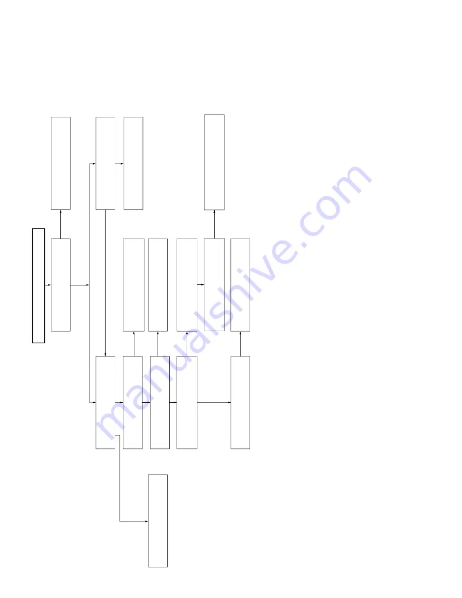
FLOW CHART NO.15
Drum servo does not function.
Check peripheral circuit of X701.
Is there 14.318MHz oscillation at
pins(37) and (38) of IC701?
NO
In PB mode
YES
In REC mode
Is there drum PG/FG signal at
pin(47).
Is the V-SYNC signal(reference) at
pin(41) of IC701?
YES
NO
NO
Check peripheral circuit of pin(41) of
IC701, C715, C7716 and R708.
Check drum PG/FG signal line.
Is the head switching pulse at pin(18)
of IC701 present?
NO
See
FLOW CHART NO.14
.
YES
YES
Is the drum-error at pin(29) of IC701
present?
NO
Replace IC701.
YES
YES
Is the drum control voltage applied
to pin(2) of IC701.
YES
Is pin(25) of IC701 in high
impedance?
NO
YES
NO
Check lines between pin(29) of
IC701 and pin(12) of P701.
Does the IC706 operate normally?
Replace IC701.
Replace drum motor.
Содержание VC-A565U
Страница 49: ...49 VC A565U H965U M E M O ...
Страница 50: ...VC A565U H965U VC A565U H965U 50 51 8 BLOCK DIAGRAM SYSTEM SERVO BLOCK DIAGRAM ...
Страница 51: ...VC A565U H965U VC A565U H965U 52 53 SIGNAL FLOW BLOCK DIAGRAM A565U ...
Страница 52: ...VC A565U H965U VC A565U H965U 54 55 SIGNAL FLOW BLOCK DIAGRAM A965U ...
Страница 53: ...56 VC A565U H965U POWER CIRCUIT BLOCK DIAGRAM ...
Страница 55: ...56 VC A565U H965U POWER CIRCUIT BLOCK DIAGRAM ...
Страница 62: ...67 VC A565U H965U A B C D E F G H I J 1 2 3 4 5 6 7 8 9 10 PWB FOIL PATTERN OPERATION PWB LCD PWB ...
Страница 64: ...70 VC A565U H965U M E M O ...


