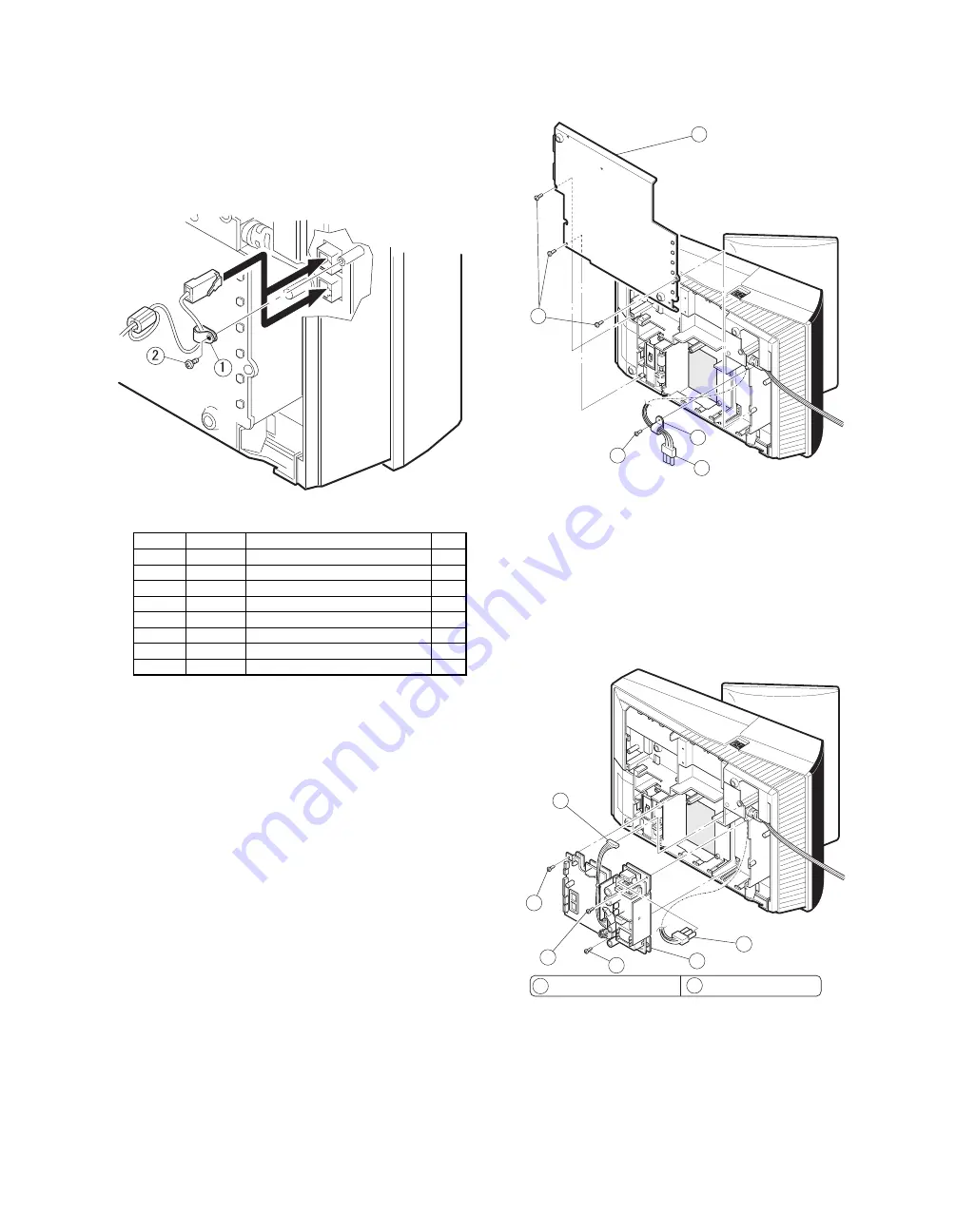
2) COM3/5, COM4/6
•
Two channels of COM port with an RJ45 connector are
equipped.
•
For 2 channels of RJ45 COM port, COM3 & COM4 or an I/O
address (COM5 & COM6) can be selected.
•
Two CABLE HOLDER
1
and SCREW (M3
×
8)
2
are con-
tained in the package.
Connector Specifications
RJ45
Pin No.
Signal
Function
I/O
1
RS
Request to Send
O
2
ER
Data terminal Ready
O
3
SD
Send Data
O
4
SG
Signal Ground
—
5
SG
Signal Ground
—
6
RD
Receive Data
I
7
DR
Data set Ready
I
8
CS
Clear to Send
I
20. BUILT-IN PRINTER: UP-T80BP
1) Remove the BOTTOM PLATE
2
.
a) Remove the three SCREWs
1
.
b) Remove the BOTTOM PLATE
2
.
c) Remove the SCREW
3
, CABLE CLAMP
4
and POWER SUPP-
LY CABLE
5
.
Fig. 1
2) Install the PS+CONTROL PWB
6
.
a) Fix the PS+CONTROL PWB
6
with three SCREWs
7
Z
,
3
*
SCREW
3
: Use the screw which was fixing the CLAMP
4
3) Connect the POWER SUPPLY CABLE
5
to the
PS+CONTROL PWB
6
. (No. CN1)
4) Connect the I/F CABLE
8
of the PS+CONTROL
PWB
6
to the UP-5300 MAIN PWB (No.CN109)
Fig. 2
2
1
3
4
5
5
6
3
7
8
: XHBSD30P06000
: XEBSD30P08000
7
30
30
– 12 –


