background image

19

SJ-2047
SJ-2050
SJ-2060

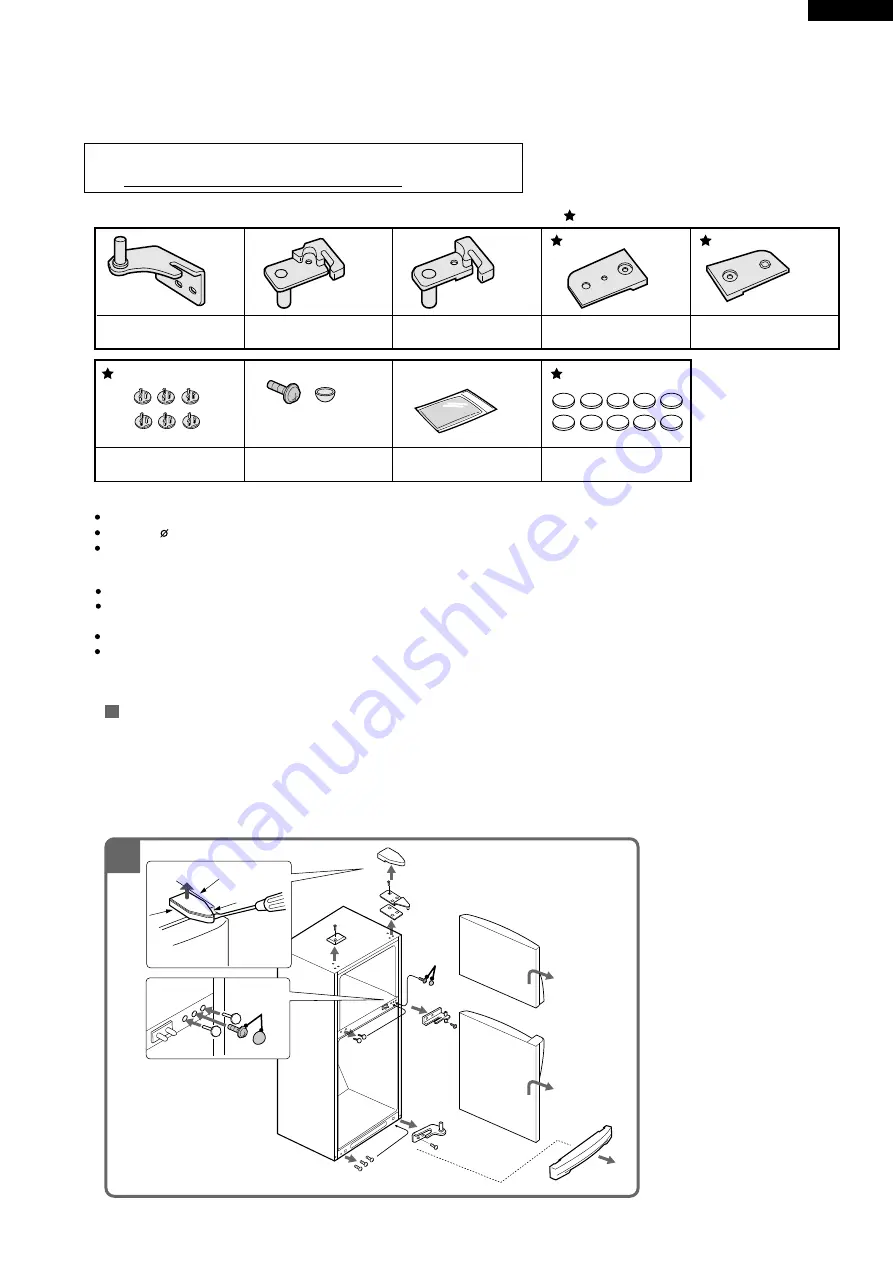
MODIFICATION PROCEDURE OF THE DOOR OPEN SIDE

It is possible to change the door to left side opening.
To modify the door to left side opening, REFRIGERATOR HINGE KITS (for left side opening) SJ-L838LD (optional item )is necessary. 

by SJ-L838LD OPERATION MANUAL

These kits are used to change the refrigerator doors from right to left opening.
if you wish to change the door to left opening for some reason, such as restricted installation
space, ask your authorized service agent for this modification.

Tools required

Parts list

Phillips and slotted screwdrivers
Drill bit (    3.8 mm)
Socket wrench or spanner (8 mm) :The socket wrench or spanner is used to detach and attach hinges.

Always disconnect the power plug from the wall outlet before performing work.
Caution should be taken when handling the doors. 
These are heavy and could cause personal injury if mishandled.
Always tighten screws securely. May cause personal injury if door becomes unlatched and falls.
Reattach doors paying careful attention to the door alignment. Failure to fit the door 
correctly might cause the cool air to leak out and lower the cooling performance.

Caution

Fitting Instruction

A

B

C

D

E

F

G

H

J

Stopper spring L 
(for upper door)

Stopper spring L
 (for lower door)

Bottom hinge L

Door cap cover 
(for upper door)

Door cap cover 
(for lower door)

Door hole cover

Screw and Cover

Silicon grease

Preparation/Removing Doors

1

  1. Remove Evaporating pan cover, Upper hinge cover, and Top cover. 
      (Carefully remove Upper hinge cover using a screwdriver, making sure that the door is not damaged.) 
  2. Remove Upper hinge and Spacer, and detach Upper door by lifting off the center hinge.
  3. Remove Center hinge and detach Lower door by lifting off the bottom hinge. Remove the 2 Hole caps, replace them on 
      the screw holes of the removed center hinge, then screw in  G (screw and cover) in the center hole.
  4. Remove Bottom hinge. Remove the 3 screws on the left side, then install them in the screw holes of Bottom hinge.

1

Select the same color as the refrigerator exterior.

G

4

4

3

3

1

1

2

3

1

2

3

G

Screw cap for handle
(Spare)

Figure M-1

Содержание SJ-2047-BE

Страница 1: ...1 MODIFICATION PROCEDURE OF THE DOOR OPEN SIDE 19 COOLING UNIT 22 REPLACEMENT PARTS LIST 24 Refrigerant HFC 134a Refer to HFC 134a COOLING UNIT Service Manual for handling this refrigerant DESTINATION W In the interests of user safety Required by safety regulations in some countries the set should be restored to its original condition and only parts identical to those specified should be used REFR...

Страница 2: ... crunching sound Sound produced by expansion and contraction of inner walls and internal parts during cooling Squeaking sound Sound produced by expansion and contraction of internal parts Sound of flowing fluid gurgling sound fizzing sound Sound of refrigerant flowing in pipes sound may become louder from time to time 3 IT IS NORMAL for the refrigerator to produce the following sounds Do not place...

Страница 3: ...Vegetable case 1 Fruit case 1 R door pocket 1 2 Egg tray 2 Bottle pocket 2 Utility case pocket 1 Chilled case 1 Tube stand 2 Freezer Freezer shelf ass y 1 Compartment Ice cube maker Twin ice cube maker Ice storage box 1 F door pocket 2 Deodorizing system Yes RATING Items SJ 2047 SJ 2050 SJ 2060 Rated voltage V 220 240 Rated frequency Hz 50 Climate class T Rated input W 170 190 Rated input of heati...

Страница 4: ...or 20 Freezer pocket F door pocket 21 Water cup 22 Magnetic door seal Door packing 23 Utility pocket Utility case pocket 24 Egg holder Egg tray 25 Free pocket R door pocket SJ 2047 2050 1 pocket SJ 2060 2 pockets 26 Bottle pocket 27 Bottle guard Tube stand 1 18 19 20 21 22 23 24 25 26 27 3 2 4 5 6 7 8 9 10 11 12 13 14 17 15 16 22 Figure D 1 External Description Upper hinge cover Hot pipe Freezer t...

Страница 5: ...als push button type Damper thermostat MM1 6170 SJ 2050 2060 Open Close 3 2 C MM1 6171 SJ 2047 Open Close 5 0 C Defrost timer TMDF904FD2 220 240V Integration type 50 60Hz Cycle time 10 8 9 0 hours 50 60Hz Delay time 4 3 3 6 min 50 60Hz Lamp socket F R 250V 1A E 12 Hard plastic body type F lamp 240V 10W E 12 R lamp 240V 15W E 12 R fan thermo R fan thermo S101 250V 8A Open Close 7 15 C ass y R fan t...

Страница 6: ...STAT R DEFROST TIMER TM THERMO FUSE FM FM DEFROST HEATER DEFROST THERMOSTAT STARTING RELAY C M A COMPRESSOR PROTECTOR B DOOR SWITCH 1 2 4 S B R FAN THERMO HEATER R FAN THERMO L L 3 O BR W Y G 4 1 2 3 CONNECTED IN TERMINAL BOX CONNECTOR G Br O Y R P B Bk S B G Y W GRAY BROWN ORANGE YELLOW RED PINK BLUE BLACK SKY BLUE GREEN YELLOW WHITE R R F F BK SOURCE CORD RUNNING CAPACITOR CAPACITOR G Y ...

Страница 7: ...MP 15W LAMP SOCKET STARTING RELAY PROTECTOR 1 2 3 4 3 1 4 2 5 7 6 8 1 2 1 2 1 2 1 2 1 2 3 4 1 2 3 4 1 2 3 4 1 2 3 4 1 2 3 4 1 2 3 4 1 L E N 1 2 3 4 5 7 6 8 9 9 GY 1 OR 1 BL 2 SB 1 SB 2 SB 3 BR 3 BR 4 OR 3 OR 2 OR 2 W 2 OR 1 OR 3 R 1 BR 2 Y 1 R 1 BK 1 GY 2 Y 1 Y 2 BL 1 BK 1 W 1 BR 1 W 2 W 1 Y 2 TERMINAL BOX C M A BROWN BLUE GRAY SKY BLUE SOURCE CORD TERMINAL COVER COMPRESSOR EARTH EARTH G Y G Br O ...

Страница 8: ...est MED MIN Approx 0 c Approx 3 c Approx 3 c Approx 1 c Approx 6 c Approx 4 c The values shown above refer to the case where the freezer temp control knob is set at MED Figure F 2 When the temperature of the refrigerator is higher R fan thermo senses the temperature and the refrigerator is cooled efficiently by running of R fan motor R fan thermo heater energizes when the door is opened intend to ...

Страница 9: ...e operation time delay time of defrost time defrosted water is drained outside the refrigerator Timer contact is changed to cooling operation and the compressor starts running and the timer motor stops Defrost thermostat contact becomes ON when it s cooled And the timer motor starts running Figure F 3 Figure F 3 Figure F 4 Figure F 5 Figure F 6 TM COMP Defrost thermostat ON Compressor running Time...

Страница 10: ...lt hot if touched by hand while the compressor is in operation If you are asked about this please explain that the hot pipe serve to prevent the dew generation Figure F 7 4 INSPECTION OF INITIAL STARTING 1 Inspection of cooling unit 1 Set the temperature control knob to MAX and check that the compressor starts to operate 2 Depress the door switch to run the fan and check that cool air is blown out...

Страница 11: ... RA sealer B RA sealer C Dial sealer RA sealer D R air guider A RA sealer A Damper thermo A sealer thermo cap Defrost timer R fan thermo ass y Figure A 1 After forming fix it to the refrigerator Figure A 2 1 Forming sensor of Damper thermo Stick thermo cap sealer Less than 130 mm Damper thermostat 3 1 mm 5 1 mm Less than 12 mm 25 2 mm NOTE Minimum bending radius is R5mm There should be no gas leak...

Страница 12: ...A sealer thermo cap RA sealer D RA sealer A RA sealer A RA sealer A Front side Back side Bottom side Dial sealer OVERLAP 15mm OVERLAP 15mm Figure A 4 10 5mm Cut R C box cover Nylon band R fan thermo ass y Fan cover Defrost timer R fan thermo ass y Nylon band SEC G G G G 3 Fixing of Defrost timer R fan thermo ass y cover to R C box cover Figure A 3 ...

Страница 13: ...fan motor holder A Fan clamp R fan motor holder B Figure A 5 1 Fixing of Lamp and Lamp socket 1 1 Screw Lamp 15W into Lamp socket 1 2 Fix Lamp socket on R lamp box by tapping screws Tapping screw Lamp socket Lamp 15W R lamp box ALMINUM TAPE Figure A 6 1 3 Insert the terminal of Lamp socket to R fan motor Figure A 7 Fan motor Lamp socket DOUBLE CLAMPING WIRES ...

Страница 14: ...motor holder B to A Propeller fan 80 R fan motor holder A R fan motor R fan motor holder B Fan clamp Propeller fan 80 F Shaft 2 3 0 5mm Fan clamp Slit Slit of each Fan clamp and Propeller fan should not be at same position Detail of F 2 4 Set Fan clamp to Propeller fan 80 and insert it to the shaft of R fan motor Figure A 9 3 Sticking Warning label Figure A 8 Lamp 15W Warning label Figure A 10 ...

Страница 15: ...r sealer C Lead E V cover ass y Fan motor holder A Fan motor holder B Propeller Fan 100 Fan clamp Motor cushion U sealer handle Fan motor Figure A 11 Figure A 12 1 Sticking of Sealers to E V cover E V cover sealer B E V cover sealer D b E V cover sealer D a E V cover sealer A E V cover Sticking start b Sticking start a Sticking start Overlap 10mm min Front side Back side Sticking start ...

Страница 16: ...to the shaft of Fan motor Fan clamp Propeller fan 100 Fan clamp Slit Slit of each Fan clamp and Propeller fan should not be at same position Shaft 4 0 5mm Detail of D D 2 2 Insert the terminals of Lead EV cover ass y to R fan motor 2 3 Fix two Motor cushions to R fan motor and set it at Fan motor holder A and B Then fix with Tapping screw Fan motor holder A Fan motor holder B Motor cushion Tapping...

Страница 17: ...al side below F F Fuse ass y E V cover Fuse ass y Lead E V cover ass y Sec F F Sec E E Not come out of claw Take out lead wire from square hole to front and seal with E V cover sealer C FRONT SIDE more than 3 5mm more than 3 5mm Figure A 16 Figure A 18 1 2 3 4 5 6 7 8 9 F thermostat 3 F thermostat 4 Fuse 8 Fuse 7 Fan motor 1 2 Fan motor 9 RED inserted BROWN inserted WHITE Defrost thermo 5 Defrost ...

Страница 18: ...lary tube of F thermostat 42mm 13mm 20mm 20mm 230mm R10mm R10mm Note Bending radius of capillary tube should be R5mm to R10mm Figure A 19 F F SEC F F 5 3 Set to E V cover Figure A 21 5 2 Insert terminal of Lead EV cover ass y RED BROWN front side back side Figure A 20 ...

Страница 19: ...r becomes unlatched and falls Reattach doors paying careful attention to the door alignment Failure to fit the door correctly might cause the cool air to leak out and lower the cooling performance Caution Fitting Instruction A B C D E F G H J Stopper spring L for upper door Stopper spring L for lower door Bottom hinge L Door cap cover for upper door Door cap cover for lower door Door hole cover Sc...

Страница 20: ...w in the screw hole on the lower right of the Lower door 5 Fix upper portion of Upper handle using one screw on the right side of Lower door then temporarily fix the handle to the door using tape 6 To open screw holes first make marks on the doorplate surface through the 3 holes of the handle then temporarily remove the handle make sure that the dimensions of the markings are as shown in the diagr...

Страница 21: ...her each door can be opened closed smoothly Whether each door is properly sealed when closed Check by inserting a sheet of paper between the door and cabinet when closing The refrigerator is not properly sealed if the paper falls 7 Apply Silicon grease H to the shaded portion of the door packing 8 Replace the cap in Evaporating pan cover on the right side 9 Reattach Evaporating pan cover Upper hin...

Страница 22: ...NG UNIT Figure C 1 Cooling unit Hot pipe L Side condenser Hot pipe DP condenser Hot pipe R Side condenser Evaporator Suction pipe Sub condenser Compressor Capillary tube Dryer Back condenser Mark Refrigerant flow Mark Brazing portion ...

Страница 23: ...nt Suction pipe to Compressor s suction pipe Suction pipe to S P connector Dryer to Capillary tube Sub condenser to Back condenser Charge pipe L to Compressor s process tube Compressor butyl Compressor Suction pipe Charge pipe Charge pipe Capillary tube Dryer Hot pipe S P connector Sub condenser Back condenser Evaporator Figure C 3 Location Figure C 2 Location ...

Страница 24: ...AVA075CBEA Center hinge spacer 1 1 1 AD 2 13 DHNG A363CBMZ Upper hinge assembly 1 1 1 AE 2 14 DHNG A365CBMZ Bottom hinge R assembly 1 1 1 AE 2 15 DHNG A364CBMZ Center hinge R assembly 1 1 1 AF 2 16 GCOV A191CBFZ E v cover 1 1 1 AS 2 17 LCRA A010CBE0 Fan clamp 2 2 2 AD 2 19 LHLD A389CBF0 Motor cushion 2 2 2 AF 2 20 NFANPA020CBFA Propeller fan 100 1 1 1 AE 2 21 PSEL B845CBEZ E v cover sealer A 1 1 1...

Страница 25: ...RFB307CBKZ F door assembly 1 BK 3 5 FDORFB308CBKZ F door assembly 1 BH 3 5 1 LSTPPA107CBFA Fd stopper spring R 1 1 1 AD 3 5 2 NBRGPA022CBFA Nylon bearing 3S 2 2 2 AC 3 5 3 PCOV A251CBFA Dc cover FR 1 AC 3 5 3 PCOV A251CBFC Dc cover FR 1 AC 3 5 3 PCOV A251CBFE Dc cover FR 1 AC 3 6 FPACGA309CBKZ F door packing 1 1 1 AX 3 7 HDECQA384CBFA Handle trim FL 1 AD 3 7 HDECQA384CBFB Handle trim FL 1 1 AG 3 8...

Страница 26: ... 1 AC 5 31 LRALPA132CBFA Ice tray holder L 1 1 1 AF 5 32 LRALPA133CBFA Ice tray holder R 1 1 1 AF 5 33 LRALPA134CBFA Ice tray holder B 1 1 1 AF 5 34 PCUP A009CBFA Water cup 1 1 1 AD 5 35 UPOKPA251CBFA Tube stand 2 2 2 AC 5 36 PCOV A259CBFA Case cover 1 1 1 AH 5 37 UPOK A167CBRA Utility case pocket 1 1 1 AM CYCLE PARTS 6 1 PCMPLA202CBEZ Compressor 1 1 1 BX 6 2 PSPAGA028CBE0 Rubber grommet 4 4 4 AD ...

Страница 27: ...A Bottom hinge spacer 1 1 1 1 1 AC 2 12 PSPAVA075CBEA Center hinge spacer 1 1 1 1 1 AD 2 13 DHNG A363CBMZ Upper hinge assembly 1 1 1 1 1 AE 2 14 DHNG A365CBMZ Bottom hinge R assembly 1 1 1 1 1 AE 2 15 DHNG A364CBMZ Center hinge R assembly 1 1 1 1 1 AF 2 16 GCOV A191CBFZ E v cover 1 1 1 1 1 AS 2 17 LCRA A010CBE0 Fan clamp 2 2 2 2 2 AD 2 19 LHLD A389CBF0 Motor cushion 2 2 2 2 2 AF 2 20 NFANPA020CBFA...

Страница 28: ...A sealer FS A 1 1 1 1 1 AC 2 106 PSEL B897CBEZ A sealer FS B 2 2 2 2 2 AC DOOR PARTS 3 5 FDORFB299CBKZ F door assembly 1 BK 3 5 FDORFB306CBKZ F door assembly 1 BM 3 5 FDORFB307CBKZ F door assembly 1 BK 3 5 FDORFB308CBKZ F door assembly 1 BH 3 5 FDORFB313CBKZ F door assembly 1 BL 3 5 1 LSTPPA107CBFA Fd stopper spring R 1 1 1 1 1 AD 3 5 2 NBRGPA022CBFA Nylon bearing 3S 2 2 2 2 2 AC 3 5 3 PCOV A251CB...

Страница 29: ...ed door 1 1 1 1 1 AP 5 24 FTNA A301CBKZ R glass shelf assembly 2 2 2 2 2 BC 5 25 FTNA A302CBKZ V glass shelf assembly 1 1 1 1 1 BC 5 26 PCAP A076CBFA Venti grille cap 1 AC 5 26 PCAP A076CBFB Venti grille cap 1 AC 5 26 PCAP A076CBFC Venti grille cap 1 AD 5 26 PCAP A076CBFE Venti grille cap 1 AD 5 26 PCAP A076CBFF Venti grille cap 1 AC 5 28 PCAP A069CBFA V sliding cap L 1 1 1 1 1 AC 5 29 PCAP A070CB...

Страница 30: ...L 2050 WH 2050 GR 2050 BE MISCELLANEOUS 90 2 TLAB A092CBR0 Lamp label 1 1 1 1 1 AD 90 3 SPAKCI798YDEZ Packing case 1 1 1 1 1 BC 90 5 TLAB A614CBE0 Case label GY 4 AD 90 5 TLAB A615CBE0 Case label BE 4 AD 90 5 TLAB A616CBE0 Case label BL 4 AD 90 5 TLAB A617CBE0 Case label WH 4 AD 90 5 TLAB A854CBE0 Case label GR 4 AG 90 6 CPADBA765YDKZ Bottom pad assembly 1 1 1 1 1 AY 90 7 CPADBA764YDKZ Top pad ass...

Страница 31: ...om hinge spacer 1 1 1 AC 2 12 PSPAVA075CBEA Center hinge spacer 1 1 1 AD 2 13 DHNG A363CBMZ Upper hinge assembly 1 1 1 AE 2 14 DHNG A365CBMZ Bottom hinge R assembly 1 1 1 AE 2 15 DHNG A364CBMZ Center hinge R assembly 1 1 1 AF 2 16 GCOV A191CBFZ E v cover 1 1 1 AS 2 17 LCRA A010CBE0 Fan clamp 2 2 2 AD 2 19 LHLD A389CBF0 Motor cushion 2 2 2 AF 2 20 NFANPA020CBFA Propeller fan 100 1 1 1 AE 2 21 PSEL ...

Страница 32: ...FDORFB307CBKZ F door ass y 1 BK 3 5 FDORFB308CBKZ F door assembly 1 BH 3 5 1 LSTPPA107CBFA Fd stopper spring R 1 1 1 AD 3 5 2 NBRGPA022CBFA Nylon bearing 3S 2 2 2 AC 3 5 3 PCOV A251CBFA Dc cover FR 1 AC 3 5 3 PCOV A251CBFC Dc cover FR 1 AC 3 5 3 PCOV A251CBFE Dc cover FR 1 AC 3 6 FPACGA309CBKZ F door packing 1 1 1 AX 3 7 HDECQA384CBFA Handle trim FL 1 AD 3 7 HDECQA384CBFB Handle trim FL 1 1 AG 3 8...

Страница 33: ... 1 AC 5 31 LRALPA132CBFA Ice tray holder L 1 1 1 AF 5 32 LRALPA133CBFA Ice tray holder R 1 1 1 AF 5 33 LRALPA134CBFA Ice tray holder B 1 1 1 AF 5 34 PCUP A009CBFA Water cup 1 1 1 AD 5 35 UPOKPA251CBFA Tube stand 2 2 2 AC 5 36 PCOV A259CBFA Case cover 1 1 1 AH 5 37 UPOK A167CBRA Utility case pocket 1 1 1 AM CYCLE PARTS 6 1 PCMPLA202CBEZ Compressor 1 1 1 BX 6 2 PSPAGA028CBE0 Rubber grommet 4 4 4 AD ...

Страница 34: ... 5 6 B C D E F G H DOOR PARTS SJ 2047 SJ 2050 SJ 2060 3 6 3 5 3 9 3 8 3 9 4 18 3 5 2 5 3 5 4 5 5 5 1 3 5 3 3 15 3 3 5 1 3 5 2 3 15 2 3 17 5 35 3 15 4 18 4 18 3 9 3 9 5 34 5 36 5 37 3 9 3 9 3 9 4 18 4 18 4 18 4 18 4 18 4 18 4 18 3 9 3 9 3 7 3 19 3 18 3 25 3 9 3 15 1 ...

Страница 35: ... CABINET PARTS SJ 2047 SJ 2050 SJ 2060 2 29 2 13 2 99 2 90 2 49 2 49 2 97 2 95 2 95 2 96 2 96 2 91 2 7 2 7 2 2 7 1 2 8 2 8 2 2 7 1 2 11 2 14 5 31 5 17 5 6 5 32 5 33 5 9 5 24 5 14 1 10 2 15 2 37 5 13 5 26 4 3 5 15 5 25 5 16 5 29 5 28 2 93 2 93 5 18 5 19 2 36 2 36 2 12 2 106 2 105 2 10 ...

Страница 36: ... 2 2 2 30 2 25 6 3 2 1 29 2 59 2 51 90 2 1 8 2 72 1 4 2 41 2 83 2 73 2 71 2 38 2 74 2 84 2 30 2 79 1 30 1 3 2 27 2 54 1 27 2 53 1 7 1 28 2 52 2 17 90 8 2 57 2 56 2 55 2 26 2 63 2 19 1 6 2 19 2 64 2 20 2 17 2 22 2 23 1 17 4 1 1 5 2 69 1 1 1 20 2 65 2 21 2 16 2 28 2 50 6 27 6 30 6 29 6 28 1 31 1 32 6 6 1 25 1 23 2 87 6 31 CABINET PARTS 2000 SHARP CORP 07K0 06E Printed in Japan 52APSW 52APTW 52APQW 5...

Отзывы: