
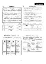

ZERLEGEN
Vorsichtsmassrsgeln
das
Beim Zerlegen und Zusammenbauen
die
pour
folgenden Anweisungen
dessen
Lors
de
et de son remontage, suivre
cherheit und ausgezeichnete Leistung aufrechtzuerhalten.
pour maintenir la
et
performances.
1.
enfernen.
1.
de
2. Vor
Zerlegen des
unbedingt den
Ausgangsstecker
H/E ziehen.
2.
pas
de retirer la fiche
d u
avant de
I’appareil.
3.
oder Leitungshalter
falls dies
beim Zerlegen
erforderlich ist.
des
darauf achten, die Leitungen wieder so
wie sie vor dem Zerlegen angeordnet
3 .
b a n d e s d e n y l o n
d e
la
reparation de
de redisposer
avant
4. Beim
von Wartungsarbeiten auf statische
der integrierten Schaltkreise und anderen
achten.
4 . F a i r e a t t e n t i o n
statique
c i r c u i t s
et
c i r c u i t s
d e l a
I
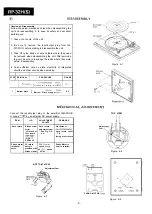
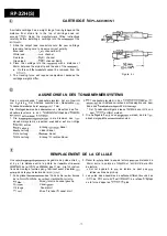
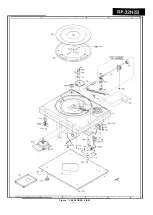
E N T F E R N E N
VERFAHREN
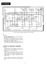
FIGURE
1
Plateau
1.
1
2.
6 - l
Anschlag
2
1
.
2.
Anschlag
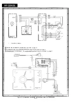
EINSTELLUNG
D e n
an den
H / E )
o d e r
la fiche
I’amplificateur
H/E), ou
courant de
CC.
ARTICLE
POINT DE
Tournevis
Came de
de retpir
33
automatique
tours ou
Voir la
disque d’essai
Fig. 6-3,
SSR-4001
6 - 4 .
ou
Disque 33
Vitesse de
V R 3 3
Vitesse de 45
4 5
scopique
SLEHRE
PUNKT
NUNG
GEN
order entgen dem
Uhrzeigersinn
der
automatischen
7 - 8
dung einer
motor dreht
automatique
Dans
ou
inverse des
d’une
Compte de
automatique:
7 8 8
un
disque
Le moteur de phono
en
rotation.
Normaler
order
SSR-4002
l
Siehe
dung 6-3,
Vitesse de
rotation
du
phono
Mit
Drehzahl
VR 33
45
4 5