


7
R -403JK
Installation
1. Remove remaining adhesive on the control panel frame surfaces with a soft cloth soaked in alcohol.
2. Make sure that the LCD sheet and the liquid crystal display is installed in position.
3. Remove the backing paper from the new membrane switch and ribbon cable.
4. Insert the ribbon cable of the membrane switch into the slit of the control panel frame.
5. Adjust the upper edge and right edge of the membrane switch to the small depression on the surface of the control panel
frame.
6. Attach the membrane switch to the control panel frame by rubbing with a soft cloth not to scratch.
7. Remove the backing paper from the new graphic sheet.
8. Adjust the upper edge and right edge of the graphic sheet to the large depression on the surface of the control panel frame.
9. Attach the graphic sheet to the control panel frame by rubbing with a soft cloth not to scratch.
10. Attach the ribbon cable to the control panel frame rear side.
11. Place the edge of the membrane switch’s ribbon cable on the lower portion of the liquid crystal display.
12. Insert the rubber connector into the long slit on the control panel frame.
13. Reinstall the control unit to the control panel frame with the three (3) screws.
NOTE:
Do not touch the contact surface of the ribbon cable (edge) and the rubber connector with a finger directly not to be
oxidized.
If display digits are missing or scrambled, remove control unit and make sure that there is not any trash or foreign
substance on the contact surface of the rubber connector. Use an adhesive tape to clean the contact surface of the
rubber connector.
(* Heat gun will soften adhesive.)
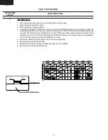
Figure C-XXX Graphic Sheet and Membrane Switch Replacement
Rub ber connector
Contact surf ace
Contact
surface
Rib bon cab le
of membr ane
s witch
Liquid cr ystal
displa y
Liquid cr ystal
displa y
Rib bon
cab le
Gr aphic
sheet
LCD sheet
Control panel fr ame
(Rear side)
Control panel fr ame
Long slit
Slit
Removal
1. Disconnect the power supply cord and then remove outer case.
2. Open the door and block it open.
3. Discharge high voltage capacitor.
4. Remove the control panel assembly, referring to chapter of CONTROL PANEL ASSEMBLY REMOVAL.
5. Remove the three (3) screws holding the control unit to the control panel frame. And remove the control unit by releasing
from tabs.
6. Remove the rubber connector from the long slit on the control panel frame.
7. Remove the night light cover (release tabs from back side).
8. Remove the graphic sheet from the control panel frame. (*See special note)
9. Remove away the membrane switch from the control panel frame. (*See special note)
Figure C-XXX Graphic Sheet and Membrane Switch Replacement
GRAPHIC SHEET AND MEMBRANE SWITCH REPLACEMENT


