background image

R-210A

5

FUNCTION OF IMPORTANT COMPONENTS

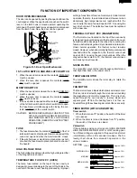
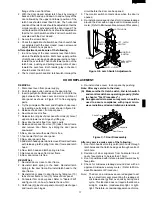
DOOR OPEN MECHANISM

The door can be opened by pushing the open button on the
control panel. When the open button is pushed, the switch
lever on the latch hook is moved upward, operating the
latch head. The latch head is moved upward, and released
from the latch hook. Now, the door can be opened.

LATCH HOOK

LATCH

HEADS

DOOR

MONITOR 
SWITCH

1ST. LATCH 

SWITCH

2ND. LATCH  

SWITCH

SWITCH LEVER

Figure D-1. Door Open Mechanism

1ST. LATCH SWITCH  AND 2ND. LATCH SWITCH

1. When the oven door is closed, the contacts (COM-NO)

must be closed.

2. When the oven door is opened, the contacts (COM-

NO) must be opened.

MONITOR SWITCH

1. When the oven door is closed, the contacts (COM-NC)

must be opened.

2. When the oven door is opened, the contacts (COM-

NC) must be closed.

3. If the oven door is opened and the contacts (COM-NO)

of the 1st latch switch and 2nd latch switch fail to open,
the fuse blows simultaneously with closing the con-
tacts (COM-NC) of the monitor switch.

CAUTION: BEFORE REPLACING A FUSE TEST THE

1ST LATCH SWITCH, 2ND LATCH SWITCH
AND MONITOR SWITCH FOR PROPER
OPERATION. (REFER TO CHAPTER "TEST
PROCEDURE".)

FUSE

1. The fuse blows when the contacts (COM-NO) of the 1st

latch switch and 2nd latch switch remain closed with the
oven door open and when the monitor switch  closes.

2. If the wire harness or electrical components are short-

circuited, the fuse blows to prevent an electric shock of
fire hazard.

HIGH VOLTAGE FUSE

The high voltage fuse blows when the high voltage rectifier
or the magnetron is shorted.

TEMPERATURE  FUSE 120˚C (OVEN)

The temp. fuse located on the top of the oven cavity is
designed to prevent damage to the oven if the foods in the
oven catch fire due to over heating produced by improper

setting of cook time or failure of control unit. Under normal
operation, the temp. fuse remains closed. However, when
abnormally high temperatures are reached within the
oven cavity, the temp. fuse will open at 120˚C, causing the
oven to shut down. The defective fuse must be replaced
with a new one.

THERMAL CUT-OUT 95˚C (MAGNETRON )

The thermal cut-out located on the top of the oven cavity
is designed to prevent damage to the magnetron if an over
heated condition develops in the tube due to cooling fan
failure, obstructed air guide, dirty or blocked air intake, etc.
Under normal operation, the thermal cut-out remains
closed. However, when abnormally high temperatures are
reached within the magnetron, the thermal cut-out will
open at  95˚C, causing the oven to shut down. When the
magnetron has cooled  to 75˚, the thermal cut-out closes
and cook cycle will resume.

NOISE FILTER

The noise filter prevents the radio frequency interference
that might flow back in the power circuit.

TURNTABLE MOTOR

The turntable motor drives the roller stay to rotate the
turntable.

FAN MOTOR

The fan motor drives a blade which draws external cool air.
This cool air is directed through the air vanes surrounding
the magnetron and cools the magnetron. This air is chan-
nelled through the oven cavity to remove steam and
vapours given off from the heating foods. It is then ex-
hausted through the exhausting air vents at the oven cavity.

TIMER MOTOR (WITH VARI-SWITCH)

Timer switch
1. When the timer is at "0" position, the switch of the timer

are opened.

2. When the timer is turned clockwise from "0" position,

the switch of the timer  are closed.

Vari-switch
If the variable cooking control is set at HIGH, MEDIUM
HIGH, MEDIUM, MEDIUM LOW or LOW cooking posi-
tion, Rated voltage is supplied to the power transformer
intermittently within a 30 seconds time base. The fol-
lowing chart shows the vari-switch operation in the
various modes.

HIGH

30 sec. ON

MEDIUM HIGH

Approx. 70%

Approx. 100%

23.2 sec. ON

6.8 sec. OFF

13.5 sec. OFF

20.2 sec. OFF

MEDIUM

Approx. 50%

16.5 sec. ON

MEDIUM LOW

Approx. 30%

9.8 sec. ON

25 sec. OFF

LOW

Approx. 10%

5.0 sec. ON

SETTING

Содержание R-210A

Страница 1: ...PLACEMENT AND ADJUSTMENT PROCEDURE 13 MICROWAVE MEASUREMENT 19 WIRING DIAGRAM 20 PICTORIAL DIAGRAM 21 PARTS LIST 22 In interests of user safety the oven should be restored to its original condition and only parts identical to those specified should be used MODEL R 210A SX737R210APT MICROWAVE OVEN SHARP CORPORATION SERVICE MANUAL MED LOW MED HIGH LOW TIMER COOKING CONTROL DOOR OPEN MED HIGH RICE DE...

Страница 2: ...R 210A ...

Страница 3: ...vice without a microwave energy absorbing load attached Never look into an open waveguide or antenna while the device is energized WARNING Never operate the oven until the following points are ensured A The door is tightly closed B The door brackets and hinges are not defective C The door packing is not damaged D The door is not deformed or warped E There is not any other visible damage with the o...

Страница 4: ...eight 295 mm including foot Depth 355 mm Cooking Cavity Dimensions Width 288 mm Height 195 mm Depth 319 mm Turntable diameter 272mm Control Complement 30 min Single Speed Timer Microwave Power for Variable Cooking Repetition Rate HIGH Full power throughout the cooking time MED HIGH MEDIUM HIGH approx 70 of FULL Power MEDIUM approx 50 of FULL Power MED LOW DEFROST approx 30 of FULL Power MEDIUM LOW...

Страница 5: ...OPEN MED HIGH RICE DEFROST 0 5 1 0 2 4 DEFROST kg RICE 1 2 3 4 1 VARIABLE COOKING CONTROL There are five power levels The approxi mate percentage of microwave power for each setting is HIGH 100 MED HIGH MEDIUM HIGH 70 MED MEDIUM 50 MED LOW DEFROST 30 MEDIUM LOW DEFROST LOW 10 2 MEAT DEFROST GUIDE 3 RICE COOKING GUIDE 4 TIMER 0 30 minutes Turn to set cooking time or weight of defrost food CONTROLPA...

Страница 6: ...timer Function sequence Figure O 2 on page 20 1 Following components are energized Power transformer H V capacitor Timer motor Magnetron H V rectifier Fan motor H V fuse Turntable motor Oven lamp 2 Rated voltage is supplied to the primary winding of the power transformer The voltage is converted to about 3 3 volts A C output on the filament winding and high voltage of approximately 2000 volts A C ...

Страница 7: ... closed However when abnormally high temperatures are reached within the oven cavity the temp fuse will open at 120 C causing the oven to shut down The defective fuse must be replaced with a new one THERMAL CUT OUT 95 C MAGNETRON The thermal cut out located on the top of the oven cavity is designed to prevent damage to the magnetron if an over heated condition develops in the tube due to cooling f...

Страница 8: ...arged about 60 seconds after the oven has been switched off Wait for 60 seconds and then short circuit the connection of the high voltage capaci tor that is of the connecting lead of the high voltage rectifier against the chassis with the use of an insulated screwdriver Sharp recommend that wherever possible fault finding is carried out with the supply disconnected It may in some cases be necessar...

Страница 9: ...blowswhenthe door is opened Home fuse blows when powercordispluggedinto wall outlet Ovendoesnotoperateatall Oven goes into cook cy cle but shuts down before end of cooking cycle Oven lamp does not light Fan motor rotates Fan motor does not oper ate but oven lamp lights Timermotordoesnotoper ate but oven lamp lights Turntablemotordoesnotop erate but oven lamp lights Oven seems to be operat ing but ...

Страница 10: ...ty vessel are at ambient temperature prior to the start of the test 3 Temperature of the water The initial temperature of the water is 10 2 C 4 Select the initial and final water temperature so that the maximum difference between the final water temperature and the ambient temperature is 5 C 5 Select stirring devices and measuring instruments in order to minimize addition or removal of heat 6 The ...

Страница 11: ...voltage Water load 2000 ml Initial temperature 23 1 C Heating time 2 min 20 sec P 60 x T Measuring method A The two water containers must be prepared The water container must be one 1 litre beaker made of Pyrex glass and its diameter approximately 12cm B Put the one 1 litre water into each beaker Each beaker has one litre water The initial temperature of the water should be 23 1 C C Mark T1 on the...

Страница 12: ...large currents are present at the secondary winding and filament winding of the power transformer It is very dangerous to work near this part when the oven is on NEVER make any voltage measurements of the high voltage circuits including the magnetron filament If the reading obtained are not stated as above then the power transformer is probably faulty and should be replaced CARRY OUT 4R CHECKS a P...

Страница 13: ...ng an ohmmeter make a continuity test across the two terminals as described in the below CARRY OUT 4R CHECKS Temperature of ON Temperature of OFF Indication of ohmmeter Parts Name condition closed circuit condition open circuit When room temperature is approx 20 C Temp fuse 120 C This is not resetable type Above 120 C Closed circuit Thermal cut out 95 C Below 75 C Above 95 C Closed circuit Table T...

Страница 14: ...RED Short circuit I TIMER MOTOR WITH VARI SWITCH TEST CARRY OUT 3D CHECKS before any of the following timer tests TIMER SWITCH CONTACTS Disconnect the leads from terminals described at following table Connect an ohmmeter across terminals described at following table Advance the timer and check that a short circuit reading is obtained on the meter Turn the timer back to the zero 0 position and chec...

Страница 15: ...gh voltage parts Magnetron High voltage transformer High volt age capacitor and High voltage rectifier assem bly 2 Hot parts Oven lamp Magnetron High voltage transformer and Oven cavity 3 Sharp edge Bottom plate Oven cavity Weveguide flange Chassis support and other metallic plate 4 Movable parts to prevent a fault Fan blade Fan motor Switch Switch lever Open button 3 Do not catch the wire leads i...

Страница 16: ... the flat type small screw driver 3 Tear the cushion from the light mount plate 4 Bend the tab of the light mount plate holding the oven 5 Lift up the oven lamp socket 6 Now the oven lamp socket is free OVEN LAMP SOCKET REMOVAL Figure C 2 Oven lamp socket POSITIVE LOCK CONNECTOR REMOVAL 1 CARRY OUT 3D CHECKS 2 Pushing the lever of positive lock connector 3 Pull out the positive lock connector CAUT...

Страница 17: ...d to the O ring and the base of the turntable motor shaft as shown in Figure C 6 4 Re install the turntable motor with the O ring and washer to the oven cavity with the single 1 screw 5 Re connect the wire leads to the turntable motor 6 Insert the tab of the turntable motor cover into the hole of the bottom plate as shown in Figure C 4 7 Re install the turntable motor cover to the bottom plate wit...

Страница 18: ... LEVER REMOVAL 1 CARRY OUT 3D CHECKS 2 Disconnect the leads from the timer motor 3 Remove the one 1 screw holding the chassis support to the front plate of the oven cavity 4 Remove the chassis support from the oven 5 Lift up the control panel and release it from the oven cavity 6 Now the control panel assembly is free 7 Open the door Remove the switch lever from the front plate of the oven cavity ...

Страница 19: ...wo 2 hole of upper and lower oven hinges by lifting up 8 Now door panel is free from oven cavity 9 Release door panel from ten 10 tabs of door frame and remove door frame by sliding the door panel downward 10 Now door panel with sealer film is free 11 Tear sealer film from door panel 12 Now door panel is free 13 Slide latch head upward and remove it from door frame with releasing latch spring from...

Страница 20: ... UPPER OVEN HINGE PIN DOOR PANEL CHOKE COVER PIN LOWER OVEN HINGE Figure C 8 Door Replacement SEALER FILM Installation 1 Put the adhesive tape on the backing film of the sealer film as shown in Fig C 9 2 Tear the backing film by pulling the adhesive tape 3 Put the pasted side of the sealer film on the door panel Sealer film Backing film Adhesive tape Figure C 9 Sealer film ...

Страница 21: ...rowave ovens must be used for test ing mW cm 2 mW cm 2 Microwave leakage measurement at 5 cm distance SHARP Recommended instruments are NARDA 8100 NARDA 8200 HOLADAY HI 1500 SIMPSON 380M 2 Place the oven tray into the oven cavity 3 Place the load of 275 15ml of water initially at 20 5 C in the centre of the oven tray The water container should be a low form of 600 ml beaker with inside diameter of...

Страница 22: ...YPASS CAPACITOR 0 0022µ AC250V THERMAL CUT OUT 95 C MG TEMP FUSE 120 C OVEN H V RECTIFIER H V CAPACITOR 0 86µ AC2000V MONITOR SWITCH 2ND LATCH SWITCH LINE BYPASS CAPACITOR 0 0022µ AC250V 1ST LATCH SWITCH OVEN LAMP OL NOISE FILTER 110V 60Hz H V FUSE 0 6A LIVE IN1 IN2 NEUTRAL EARTH NOISE SUPPRESSION COIL FUSE 13A LINE CROSS CAPACITOR 0 22µ AC125V DISCHARGE RESISTOR 180 kΩ 0 5 W VARISTOR 15G 270 V LI...

Страница 23: ... THERMALCUT OUT 95 C MG NO COM TIMER MOTOR ORG BLK RED 6 5 2 1 4 3 WHT N O ORG BLK GRY HIGH VOLTAGE COMPONENTS MAGNETRON H V FUSE HIGH VOLTAGE CAPACITOR H V RECTIFIER FAN MOTOR GRY ORG POWER TRANSFORMER WHT BLU BLU GRY RED ORG WHT RED O R G O R G O R G IN1 IN2 AC2 AC1 RED WHT BLU BLK OVEN LAMP AND SOCKET BLUE MARK NOTE Hot RED wire must be connected to the terminal with blue mark on the oven light...

Страница 24: ...CA050WRE0 Open button spring 1 AB OVEN PARTS 4 1 PHOK A086WRF0 Latch hook 1 AQ 4 2 LANGQA470WRW0 Light mount plate 1 AV 4 3 PCUSUA194WRP0 Cushion 1 AC 4 4 LBNDKA095WRP0 Capacitor holder 1 AM 4 5 NFANJA029WRE0 Fan blade 1 AL 4 6 PDUC A623WRP0 Fan duct 1 AK 4 7 FOVN A411WRT0 Oven cavity 1 BL 4 8 GLEGPA062WRF0 Leg 1 AK 4 9 LANGTA318WRP0 Chassis support 1 AQ 4 10 MLEVPA206WRF0 Switch lever 1 AL 4 11 P...

Страница 25: ...32000 Nut 4mm x 3 2mm 2 AA 7 13 XWVSD40 05000 Washer 4mm x 0 5mm 1 AA HOW TO ORDER REPLACEMENT PARTS To have your order filled prompty and correctly please furnish the following information PACKING AND ACCESSORIES 1 MODEL NUMBER 2 REF NO 3 PART NO 4 DESCRIPTION INFORMATION FOR PARTS CHANGE The foot will be changed as follows and new parts will be used for products from serial number 9712xxxxx Inte...

Страница 26: ... 13 4 3 4 2 4 15 1 13 7 2 1 9 7 9 2 1 6 6 6 5 4 12 7 7 7 7 7 7 7 7 7 9 4 5 4 20 4 14 1 4 7 8 7 2 4 6 7 5 1 7 1 6 7 2 1 15 1 1 8 6 8 7 12 7 7 4 9 7 8 4 17 7 10 4 1 1 2 1 2 1 3 4 10 1 12 7 3 4 8 7 7 2 3 2 3 7 7 7 7 7 7 2 2 7 2 1 11 4 16 7 4 4 11 4 7 6 1 4 18 6 2 7 6 7 2 6 7 7 2 1 15 4 4 1 16 7 11 1 14 7 13 6 10 ...

Страница 27: ...3 6 4 5 1 2 3 A B C D E F G H A B C D E F G H DOOR PARTS MISCELLANEOUS CONTROL PANEL PARTS 5 3 5 2 3 2 3 4 3 3 7 1 3 5 3 1 1 1 5 4 5 5 6 4 5 7 5 7 5 6 5 8 5 1 5 7 Actual wire harness may be different than illustration 6 9 ...

Страница 28: ...R 210A 26 97SHARP CORP 11K0 100E Printed in Japan ...

Отзывы: