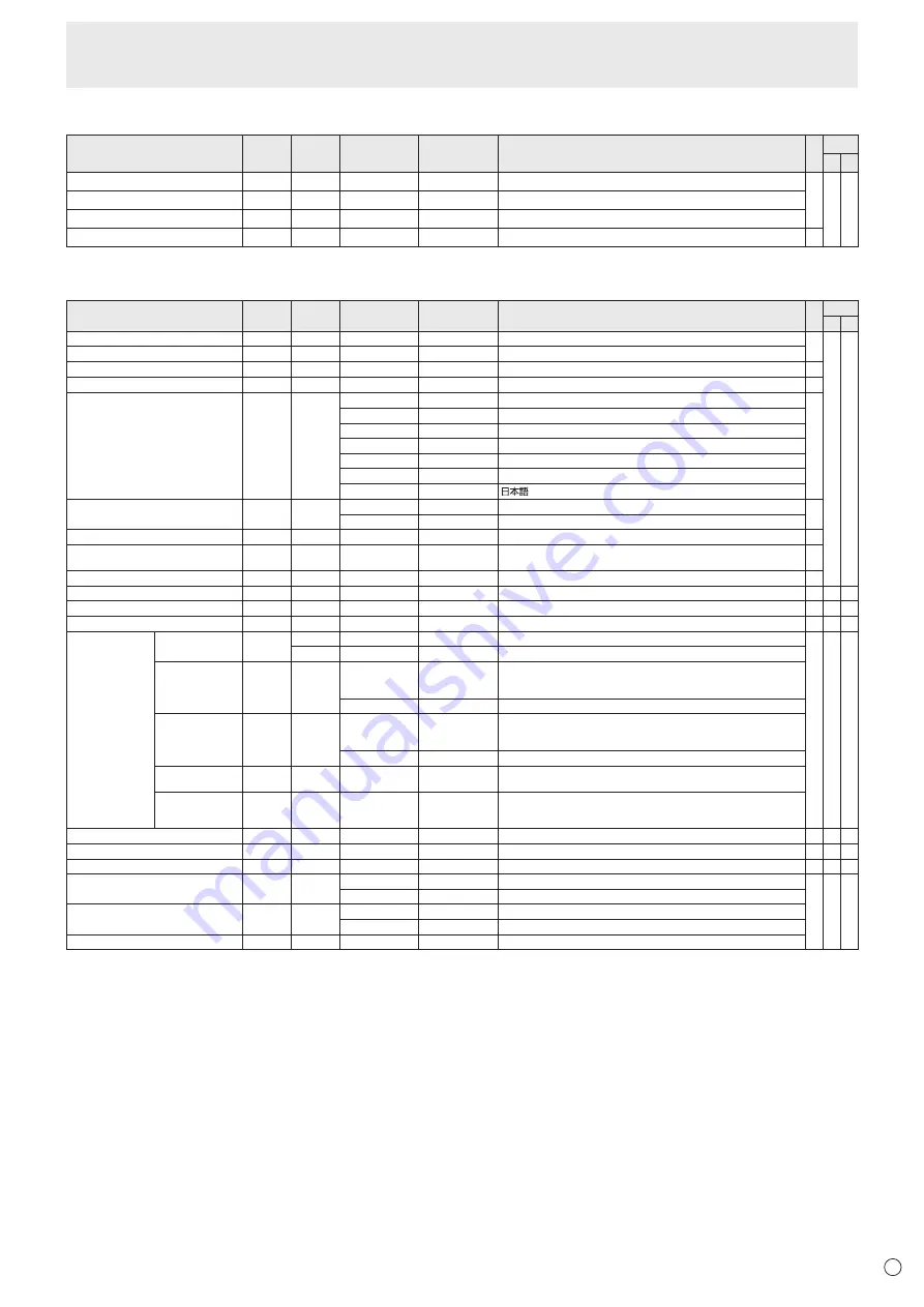
background image

37

E

AUDIO menu

Function

Command Direction

Parameter

Reply

Control/Response contents

*1

*2

(A) (B)

TREBLE

AUTR

WR

-5-5

-5-5

○ ○ ○

BASS

AUBS

WR

-5-5

-5-5

BALANCE

AUBL

WR

-10-10

-10-10

RESET

ARST

W

3

-

SETUP menu

Function

Command Direction

Parameter

Reply

Control/Response contents

*1

*2

(A) (B)

OSD H-POSITION 

OSDH

WR

0-100

0-100

○ ○

OSD V-POSITION

OSDV

WR

0-100

0-100

MONITOR

STDR

WR

0-1

0-1 0: LANDSCAPE, 1: PORTRAIT

MONAURAL AUDIO

MONO

WR

0-1

0-1 0: OFF, 1: ON

LANGUAGE

LANG

WR

14

14 ENGLISH

1

1 DEUTSCH

2

2 FRANÇAIS

3

3 ITALIANO

4

4 ESPAÑOL

5

5

РУССКИЙ

6

6


POWER ON DELAy

PWOD

WR

0

0 OFF

1-60

1-60 ON

OPERATION MODE

FNCM

WR

0-1

0-1 0: MODE1, 1: MODE2

STANDBy MODE

STBM

WR

0-1

0-1 0: STANDARD, 1: LOW POWER

(“ERR" when SCHEDULE is effective or OFF is selected for LED.)

OFF IF NO OPERATION

ATOF

WR

0-1

0-1 0: OFF, 1: ON

HOT PLUG CONTROL (DVI)

HPCT

WR

0-1

0-1 0: OFF, 1: ON

-

HOT PLUG CONTROL (HDMI)

HPCH

WR

0-1

0-1 0: OFF, 1: ON

○ ○ ○

RS-232C/LAN SELECT

CTLS

WR

0-1

0-1 0 : RS-232C 1 : LAN

-

ID NUMBER

ID NO. SETTING

IDST

W

0-255

Sets the monitor’s ID number. (“0” means “no ID number”.)

○ ○ ○

R

0-255 Returns the monitor’s ID number.

ID NO. SETTING 

(ONCE)

IDSL

W

1-255

Sets a monitor ID number.

This ID number is only effective for the command immediately after this 

command.

0

Clears the ID number if one has been designated.

ID NO. SETTING 

(SUBSEQUENT)

IDLK

W

1-255

Sets a monitor ID number. 

This ID number is effective for the next and all subsequent commands 

after this command.

0

Clears the ID number if one has been designated.

ID CHECK

IDCK

W

0 ID 

: xxx 

IDLK  : yyy

Displays monitor’s own ID number and the selected ID number on the 

screen.

ID DISPLAy

IDDP

W

0-2

0: OFF, 1: ON, 2: ON (turns OFF after 4 sec.)

(When the PN-ZB01 is attached, the IP address and MAC address are 

both displayed.)

BAUD RATE

BAUD

WR

0-2

0-2 0: 9600bps, 1: 19200bps, 2: 38400bps

○ ○ ○

SPEAKER SELECT

SPSL

WR

0-1

0-1 0: Internal speaker, 1: External speaker

-

HDMI AUTO VIEW

HDAW

WR

0-1

0-1 0: OFF, 1: ON

○ ○ ○

SETTING COPy MODE

CPMD

WR

0

0 Copy to all monitors.

○ ○ ○

1-225

1-225 Copy to the monitor with the set ID Number.

SETTING COPy TARGET

CPTG

WR

0

0 Copies the PICTURE menu settings.

1

1 Copies all the settings.

LOGO SCREEN

BTSC

WR

0-1

0-1 0: OFF, 1: ON

Controlling the Monitor with a PC (RS-232C)

Содержание PN-E702

Страница 1: ...PN E702 LCD MONITOR OPERATION MANUAL ...

Страница 2: ...oceed as follows The wire which is coloured GREEN AND YELLOW must be connected to the terminal in the plug which is marked by the letter E or by the safety earth or coloured green or green and yellow The wire which is coloured BLUE must be connected to the terminal which is marked with the letter N or coloured black The wire which is coloured BROWN must be connected to the terminal which is marked...

Страница 3: ...difications to this equipment not expressly approved by the manufacturer could void the user s authority to operate this equipment NOTE This equipment has been tested and found to comply with the limits for Class A digital device pursuant to Part 15 of the FCC Rules These limits are designed to provide reasonable protection against harmful interference when the equipment is operated in a commercia...

Страница 4: ...www swico ch or www sens ch B Information on Disposal for Business Users 1 In the European Union If the product is used for business purposes and you want to discard it Please contact your SHARP dealer who will inform you about the take back of the product You might be charged for the costs arising from take back and recycling Small products and small amounts might be taken back by your local coll...

Страница 5: ... or objects from resting on them 10 The LCD panel used in this product is made of glass Therefore it can break when the product is dropped or applied with impact Be careful not to be injured by broken glass pieces in case the LCD panel breaks 11 Overloading Do not overload AC outlets or extension cords Overloading can cause fire or electric shock 12 Entering of objects and liquids Never insert an ...

Страница 6: ...onment this product may cause radio interference in which case the user may be required to take adequate counter measures To maintain compliance with EMC regulations use shielded cables to connect to the following terminals PC AV DVI D output terminal PC AV DVI D input terminal PC AV HDMI input terminal PC D SUB input terminal PC RGB input terminals and RS 232C input output terminals If a monitor ...

Страница 7: ...u will need to prepare appropriately orientated content in advance The AC outlet shall be installed near the equipment and shall be easily accessible The Power Cord Use only the power cord supplied with the monitor Do not damage the power cord nor place heavy objects on it stretch it or over bend it Also do not add extension cords Damage to the cord may result in fire or electric shock Do not use ...

Страница 8: ...e installation of the monitor inside a housing or if the ambient temperature may be outside of the range of 32 F 0 C to 104 F 40 C install a fan or take other measures to keep the ambient temperature within the required range Temperature condition may change when using the monitor together with the optional equipments recommended by SHARP In such cases please check the temperature condition specif...

Страница 9: ... 8 Supplied Components 9 Part Names 10 Connecting Peripheral Equipment 12 Connection with a PC or AV equipment 12 Connection when the PN ZB01 optional is attached 13 Connecting the Power Cord 14 Binding Cables 14 Removing the Handles 14 Preparing the Remote Control Unit 15 Installing the batteries 15 Remote control operation range 15 Turning Power On Off 16 Turning on the main power 16 Turning pow...

Страница 10: ...nput terminal See page 12 9 Audio output terminals See page 12 10 RS 232C output terminal See page 12 11 RS 232C input terminal See page 12 12 Optional terminal This terminal is provided for possible future optional function expansion Offering of this terminal is not a guarantee that future expanded functionality will be provided 13 AC input terminal See page 14 14 Main power switch See page 16 Ca...

Страница 11: ...smitter 2 POWER button See page 16 3 MUTE button See page 18 4 VOL buttons See page 18 BRIGHT buttons See page 18 Cursor control buttons 5 DISPLAY button See page 18 6 MODE button See page 18 7 INPUT button See page 18 8 MENU button See page 18 9 SIZE button See page 18 ...

Страница 12: ...minal Factory setting PC D SUB PC DVI D PC RGB Audio input terminal AV DVI D Audio1 input terminal AV component BNC AV S video AV video BNC Audio2 input terminal AV COMPONENT D SUB AV video D SUB Audio input terminal PC HDMI AV HDMI PC AV HDMI input terminal Connection with a PC or AV equipment 1 PC AV HDMI input terminal Use a commercially available HDMI cable conforming to the HDMI standard Set ...

Страница 13: ...n the OPTION menu 12 LAN terminal You can control the monitor from a PC on a network by connecting a commercially available LAN cable between this terminal and a network 13 External speaker terminals To use external speakers set SPEAKER SELECT on the SETUP menu to EXTERNAL Be sure to use external speakers with an impedance of 6 Ω or greater and a rated input of at least 7 W 1 3 2 Approx 3 15 16 in...

Страница 14: ...lamp into the cable clamp attachment on the rear of the monitor and fasten the cables AC input terminal 1 Main power switch Power cord Supplied For power outlet 2 3 Removing the Handles The installation position can be changed Cable clamp Cable clamp attachment Cable The handles can be removed Handle Handle screws Caution The removable handles and handle screws are for use with this monitor Do not...

Страница 15: ...x 16 4 feet 5 m at an angle of approx 10 from the center to the top bottom right left of the remote control sensor 10 10 10 10 Remote control sensor 16 4 feet 5 m TIPS Do not expose the remote control unit to shock by dropping or stepping on it This could lead to a malfunction Do not expose the remote control unit to liquids and do not place it in an area with high humidity The remote control unit...

Страница 16: ...switch to turn the power ON OFF Power LED Status Status of the monitor Green lit Power on Orange lit Power off Standby mode Green flashing Input signal waiting mode Caution When switching the main power switch or the POWER button off and back on always wait for at least 5 seconds A short interval may result in a malfunction TIPS When the main power switch is off the monitor cannot be turned on If ...

Страница 17: ...e and press or to change the numerical values 2 Press or to select SET and then press MENU Be sure to set the date and time The date time setting screen will close automatically if no operation is performed for about 15 seconds The date and time can be set using DATE TIME SETTING from the OPTION menu when the date time setting screen disappears TIPS Set the date in Day Month Year order Set the tim...

Страница 18: ...previous level 3 MENU Displays and turns off the menu screen see page 20 4 VOL Volume adjustment Pressing or displays the VOLUME menu when the menu screen is not displayed V O L U M E 15 Press or to adjust the volume of the sound If you do not press any buttons for about 4 seconds the VOLUME menu automatically disappears 5 BRIGHT Backlight adjustment Pressing or displays the BRIGHT menu when the m...

Страница 19: ...lay functions to compress or expand the screen for commercial or public viewing in establishments like cafes or hotels may infringe on the rights of the creators as protected by Copyright Law so please be careful When Enlarge is set the screen size is fixed to WIDE mode When dual screen display is selected the screen size cannot be changed The appearance of the original video may change if you sel...

Страница 20: ...TION PIP PbyP MULTI O SETUP OK MENU MOVE OSD DISPLAY 1 9 2 0 x 1 0 8 0 V 60 Hz H 67 5 kHz For items that have press make settings and then press MENU 5 Press MENU twice to close the menu screen TIPS The menu will differ depending on the input mode The menu screen will close automatically if no operation is performed for about 15 seconds DATE TIME SETTING SCHEDULE and LAN SETUP screens will close i...

Страница 21: ...ion each time DISPLAY is pressed AUTO PC D SUB PC RGB The ANALOG GAIN and ANALOG OFFSET are automatically adjusted Pressing performs adjustment ANALOG GAIN PC D SUB PC RGB Adjusts the bright portions of the video input signal ANALOG OFFSET PC D SUB PC RGB Adjusts the dark portions of the video input signal BRIGHT Adjusts the backlight brightness In PIP mode the main side setting is reflected in th...

Страница 22: ... values of the PICTURE menu items to the factory preset values Select ON and then press MENU nAUDIO TREBLE Adjusts the volume of treble level sound BASS Adjusts the volume of bass level sound BALANCE Adjusts the balance of the audio sound between right and left RESET Resets the values of the AUDIO menu items to the factory preset values Select ON and then press MENU nSETUP OSD H POSITION Adjusts t...

Страница 23: ...INES AUTO 640x480 or 848x480 768 LINES AUTO 1024x768 1280x768 or 1360x768 1050 LINES 1400x1050 or 1680x1050 ZOOM2 SPECIAL SETTING See page 26 STANDBY MODE When STANDARD is selected startup time from standby mode is reduced Note however that more power will be consumed in standby mode When LOW POWER is selected current consumption is reduced while the monitor is in standby mode Note however that th...

Страница 24: ...tc depending on the signal adjustment may not be possible In this case select OFF Perform manual adjustment of the screen AUTO INPUT CHANGE Specify whether to change inputs automatically When ON is selected and no signal is present in the selected input mode AUTO INPUT CHANGE automatically changes the selected mode to another mode where a video signal is present When video signals exist in multipl...

Страница 25: ...when OFF is selected for LED in FUNCTION When displaying the color pattern it is possible to adjust certain items of the PICTURE menu Non adjustable items cannot be selected Audio input from the HDMI input terminal is also not output nDual screen display You can display the screens of the PC input signal and AV input signal simultaneously Set this function with PIP MODES in the PIP PbyP menu PIP M...

Страница 26: ... separated image to be displayed on each monitor in ENLARGE POS 1 Press 2 Press or to select position then press MENU TIPS When Enlarge is used the AUTO INPUT CHANGE function is disabled When Enlarge is used the HDMI AUTO VIEW function is disabled Menu Items nZOOM2 SPECIAL SETTING If you connect a laptop computer with any of the following screen resolutions and black bands appear around the screen...

Страница 27: ...e week 4 TIME Specifies the time to execute the SCHEDULE Set the time on a 24 hour basis Factory default Can be entered as 12 hour time using the TIME setting in DATE TIME FORMAT 5 INPUT Specifies the input mode at power on When not specifying the screen at the previous power off appears Input modes displayed on DVI HDMI BNC and D SUB depend on INPUT SELECT settings 6 BRIGHT Sets the brightness wh...

Страница 28: ... to PC RGB and display the adjustment pattern See the description below 2 Press MENU and use or to display the SCREEN menu 3 Press and select AUTO 4 Press The automatic adjustment is complete in several seconds 5 Press MENU twice to close the menu screen TIPS If the screen cannot be adjusted properly with one automatic adjustment repeat the automatic adjustment two or three times Try manual adjust...

Страница 29: ...low control via RS 232C or LAN see pages 30 and 42 Initialization Reset Functional Restriction Setting FUNCTION OSD DISPLAY Shows hides the menu modes and messages The FUNCTION screen cannot be hidden ON 1 Shows all menus modes and messages ON 2 Hides messages automatically displayed by the display Shows messages during operation OFF Hides all menus modes and messages LED Specifies whether to ligh...

Страница 30: ... RS 232C input terminal RS 232C output terminal Communication conditions Set the RS 232C communication settings on the PC to match the monitor s communication settings as follows Baud rate Stop bit 1 bit Data length 8 bits Flow control None Parity bit None Set to the same baud rate as the BAUD RATE setting of SETUP menu Initial setting 38400 bps When connecting multiple monitors in a daisy chain s...

Страница 31: ...nt use using the operation lock function see page 29 E C D K O L Return code 0DH 0AH When RS 232C LAN SELECT is set to LAN U N S E L E C T E D Return code 0DH 0AH nCommunication interval After OK or ERR is returned you must send the following commands To set a timeout for the command response specify 10 seconds or longer When connecting multiple monitors in a daisy chain set the timeout to at leas...

Страница 32: ...or with ID number 2 VOLM0020 Sets volume to 20 OK 001 The volume of the monitor with ID number 1 the one directly connected to the PC is set to 20 The IDSL command is effective only once for the immediately succeeding command IDLK The parameter of this command sets the ID number of the monitor The monitor is subject to all subsequent commands Example IDLK0002 Following commands are for the monitor...

Страница 33: ...Use the user data transfer commands UGRW UGGW and UGBW For each of the R G and B colors divide the total 512 pieces of user data into 16 blocks and transfer 32 pieces of data with each command C1 C2 C3 C4 P1 P2 P3 P4 S1 S2 Command field Block number 01 to 16 Data field Checksum field Example To transfer the data of block 1 0 to 31 levels of red R data UGRW01000000010002 0031C0 Command Block number...

Страница 34: ...ction Function Command Direction Parameter Reply Control Response contents 1 2 A B POWER CONTROL POWR W 0 Switches to standby mode 1 Returns from standby mode R 0 Standby mode 1 Normal mode 2 Input signal waiting mode INPUT MODE SELECTION INPS W 0 Toggle change for input mode Terminals not selected in INPUT SELECT cannot be selected 1 PC DVI D ERR when AV DVI D is selected for DVI of INPUT SELECT ...

Страница 35: ...0 100 0 800 on PC D SUB PC RGB Varies depending on the signal Position of the shortest direction VPOS WR 0 100 0 100 0 200 on PC D SUB PC RGB Varies depending on the signal size size of the longest direction HSIZ WR 0 100 0 100 size of the shortest direction VSIZ WR 0 100 0 100 RESOLUTION Longest direction resolution HRES WR 300 1920 300 1920 When the input mode is PC D SUB PC RGB Only even number...

Страница 36: ... W 2 Resets the saturation C M S VALUE CMVR WR 10 10 10 10 R CMVY Y CMVG G CMVC C CMVB B CMVM M CRST W 3 Resets the brightness COLOR MODE BMOD WR 0 0 STD 2 2 VIVID 3 3 sRGB When the input mode is PC 4 4 HIGH ILLUMINANCE WHITE BALANCE THRU CTMP WR 0 0 When the input mode is PC DVI D PC HDMI PRESET 1 18 1 18 From 1 approximately 3 000K to 15 approximately 10 000K 500K steps 16 approximately 5 600K 1...

Страница 37: ...e monitor s ID number 0 means no ID number R 0 255 Returns the monitor s ID number ID NO SETTING ONCE IDSL W 1 255 Sets a monitor ID number This ID number is only effective for the command immediately after this command 0 Clears the ID number if one has been designated ID NO SETTING SUBSEQUENT IDLK W 1 255 Sets a monitor ID number This ID number is effective for the next and all subsequent command...

Страница 38: ... RCA PC D SUB ASAP WR 1 3 1 3 1 AUDIO STEREO MINI 2 AUDIO1 RCA 3 AUDIO2 RCA PC RGB ASCP WR 1 3 1 3 1 AUDIO STEREO MINI 2 AUDIO1 RCA 3 AUDIO2 RCA AV DVI D ASDA WR 1 3 1 3 1 AUDIO STEREO MINI 2 AUDIO1 RCA 3 AUDIO2 RCA AV HDMI ASHA WR 0 1 0 1 0 HDMI 1 AUDIO STEREO MINI 2 3 2 3 2 AUDIO1 RCA 3 AUDIO2 RCA AV COMPONENT BNC ASCA WR 1 3 1 3 1 AUDIO STEREO MINI 2 AUDIO1 RCA 3 AUDIO2 RCA AV COMPONENT D SUB A...

Страница 39: ...MODE setting and the IMAGE POSITION The shortest direction EPSV WR 999 999 999 999 BEZEL ADJUST BZCO WR 0 1 0 1 0 OFF 1 ON BEZEL ADJUST TOP BZCT WR 0 1 0 1 0 OFF 1 ON BOTTOM BZCB WR 0 1 0 1 0 OFF 1 ON RIGHT BZCR WR 0 1 0 1 0 OFF 1 ON LEFT BZCL WR 0 1 0 1 0 OFF 1 ON BEZEL WIDTH TOP BZWT WR 0 100 0 100 BOTTOM BZWB WR 0 100 0 100 RIGHT BZWR WR 0 100 0 100 LEFT BZWL WR 0 100 0 100 ENLARGE IMAGE POSITI...

Страница 40: ...S Main screen MWPP WR 0 1 0 1 0 POS1 1 POS2 PbyP2 POS Sub screen MW2P WR 0 2 0 2 0 POS1 1 POS2 2 POS3 AUTO OFF MOFF WR 0 1 0 1 0 MANUAL 1 AUTO Initialization Functional Restriction Setting FUNCTION menu Function Command Direction Parameter Reply Control Response contents 1 2 A B ALL RESET RSET W 0 0 ALL RESET 0 1 0 ALL RESET 1 1 ALL RESET 2 ADJUSTMENT LOCK ALCK WR 0 2 0 2 0 OFF 1 ON1 2 ON2 ADJUSTM...

Страница 41: ...6 is returned CAUSE OF LAST STANDBY MODE STCA W 0 Initialization R 0 No detectable error has occurred 1 Standby mode by POWER button 2 Main power off by the main power switch 3 Standby mode by RS 232C or LAN 4 Input signal waiting mode by No Signal 6 Standby mode by abnormal temperature 8 Standby mode by SCHEDULE setting 20 Standby mode by OFF IF NO OPERATION setting Commands for setting of the GA...

Страница 42: ...Set the monitor s IP address and subnet mask to match the settings of your LAN These settings can be made on either the monitor or a PC connected to the monitor The settings depend on the configuration of your LAN Ask your LAN administrator for details To set on the monitor Set RS 232C LAN SELECT on the SETUP menu to LAN and then set the LAN SETUP options See page 23 After setting each item select...

Страница 43: ... note of the current IP address subnet mask and default gateway settings Make sure you write this information now as you will be changing the IP address subnet mask and default gateway settings back to these settings afterwards 7 Temporarily change the IP address and subnet mask To access the monitor as it is shipped from the factory set as follows IP Address 192 168 150 1 Subnet Mask 255 255 255 ...

Страница 44: ...t follows can be assigned automatically See page 23 Controlling with a PC Basic operation You use Internet Explorer on a PC on the LAN to control the monitor 1 Launch Internet Explorer on the PC 2 In the Address box type http followed by your monitor s IP address followed by then press the Enter key You can confirm the IP address with the DISPLAY function When prompted to enter a user name and pas...

Страница 45: ...DJUSTMENT You can adjust these settings which are also available on the monitor s menu SCREEN See page 21 PICTURE See page 21 PICTURE ADVANCED See page 28 AUDIO See page 22 SETUP See page 22 OPTION See page 23 SCHEDULE See page 27 MULTI See page 24 PIP PbyP See page 25 FUNCTION See page 29 TIPS After changing DISPLAY COLOR PATTERN to OFF click Refresh to correctly retrieve the status of the monito...

Страница 46: ...et manually the IP addresses of the monitor connected to the RS 232C output terminal and the daisy chain of connected monitors that follows can be assigned automatically See page 23 NETWORK SECURITY This screen allows you to specify the security related settings USER NAME PASSWORD Sets up a user name and password to restrict access to this monitor After entering a user name and password click Appl...

Страница 47: ...TOR This screen allows you to configure the e mail sent periodically or when the monitor has an error The settings depend on the configuration of your LAN Ask your LAN administrator for details SMTP SERVER Specify the SMTP server address for sending e mail When using a domain name make sure to specify the DNS server as well See page 46 ORIGINATOR E MAIL ADDRESS Specify the e mail address for this ...

Страница 48: ...il which notifies a temperature or status error TIPS The RECIPIENT E MAIL ADDRESSES can be up to 64 alphanumeric characters or symbols Controlling the Monitor with a PC LAN MAIL PERIODICAL When PERIODICAL for CONDITION of MAIL RECIPIENT is checked set the date and time to send the mail DAY OF THE WEEK Specify the day of the week to send the periodical mails TIME Specify the time of the day to send...

Страница 49: ...in power switch When the monitor restarts wait about 30 seconds and then start the next operation If the IP address is changed while the SNMP function is operational turn off the monitor and then turn it on again with the main power switch TIPS Depending on the SNMP settings a short delay may occur before the SNMP is usable About 2 minutes Up to 16 alphanumeric letters and symbols can be used for ...

Страница 50: ...PC AV DVI D input terminal does not appear properly Is the setting for DVI of INPUT SELECT on the OPTION menu correct See page 23 Is the input signal compatible with this monitor See page 54 Turn off the power to the connected equipment and then turn the power on again If the monitors are connected in a daisy chain turn off the power to all the monitors connected in a daisy chain and then turn the...

Страница 51: ...cally enters standby mode The Power LED continues flashing red and green alternately Remove the cause of the excessive temperature rise If the monitor enters standby mode due to a rise in temperature to return to normal display turn the power switch off and then back on again The monitor however will enter standby mode again if the cause of the temperature rise is not eliminated See page 8 Check w...

Страница 52: ...tal DVI D 24 pin x 1 External speaker 7 W 7 W 6 Ω LAN terminal When PN ZB01 optional is attached 10 BASE T 100 BASE TX Speaker output 7 W 7 W Power requirement AC 100 V 240 V 2 8 A 50 60 Hz Operating temperature 3 32 F to 104 F 0 C to 40 C Operating humidity 20 to 80 no condensation Power consumption Maximum input signal waiting mode 4 standby mode 5 235 W 1 0 W 1 0 W Power consumption When PN ZB0...

Страница 53: ...ht of the monitor nPower management This monitor conforms to VESA DPMS and DVI DMPM Both your video card and computer must support the same standard in order for the monitor s power management function to work DPMS Display Power Management Signaling DPMS Screen Power consumption Hsync Vsync ON STATE Display 235 W 1 Yes Yes STANDBY No display 1 0 W 1 2 No Yes SUSPEND Yes No OFF STATE No No 1 When P...

Страница 54: ...35 76MHz Yes Yes Yes Yes Yes Yes Yes Yes Yes Yes Yes Yes Yes Yes Yes Yes Yes Yes Yes Yes Yes Yes Yes Yes Yes Yes Yes Analog D SUB RGB 2 Yes Yes Yes Yes Yes Yes Yes Yes Yes Yes Yes Yes Yes Yes Yes Yes Yes Yes Yes Yes Yes Yes Yes Yes Yes Yes Yes Yes Yes Yes Yes Yes Yes Yes Yes Yes DVI 2 HDMI Yes Yes Yes Yes Yes Yes Yes Yes Yes Yes Yes Yes Yes Yes Yes Yes Yes Yes Yes Yes Yes Yes Yes 1 Displays a redu...

Страница 55: ...VI D 24 pin No Function No Function 1 TMDS data 2 13 N C 2 TMDS data 2 14 5V 3 TMDS data 2 4 shield 15 GND 4 N C 16 Hot plug detection 5 N C 17 TMDS data 0 6 DDC clock 18 TMDS data 0 7 DDC data 19 TMDS data 0 5 shield 8 N C 20 N C 9 TMDS data 1 21 N C 10 TMDS data 1 22 TMDS clock shield 11 TMDS data 1 3 shield 23 TMDS clock 12 N C 24 TMDS clock nPC AV HDMI input terminal pins HDMITM Connector No F...

Страница 56: ...ast 4 times or more the weight of the monitor Install by the most suitable method for the material and the structure To attach a VESA compliant mounting bracket use M6 screws that are 5 16 inch 8 mm to 3 8 inch 10 mm longer than the thickness of the mounting bracket When moving the monitor be sure to hold it with the handles and the unit bottom Do not hold the LCD panel This may cause product dama...

Страница 57: ...PN E702 Me EN11K 1 ...

Отзывы: