


SHARP PC-G850V(S) User Manual -
Appendix A: 11-Pin Interface
14
PIO-Mode
The PIO-mode is primarily intended for the purpose of controlling external digital
hardware, rather than for data communication with other devices. With this mode you
change the pocket computer into a microcontroller with an on-board development
environment.
The 11-pin interface becomes a programmable 8-bit port. The logic levels (LOW/HIGH)
can be set and read by the PIO-API (API = Application Programming Interface) in BASIC
or C. Each of the 8 signals/bits can be configured individually to serve as input or output.
The direction can be set by the function
pioset/PIOSET
(see command reference).
The function
pioput/PIOPUT
sets the individual logic levels of each signal by setting
the respective bit to 0 (=LOW) or 1 (=HIGH). Signals that were configured as input are
ignored then. The function
pioget/PIOGET
reads all 8 logic levels of the port into one
byte.
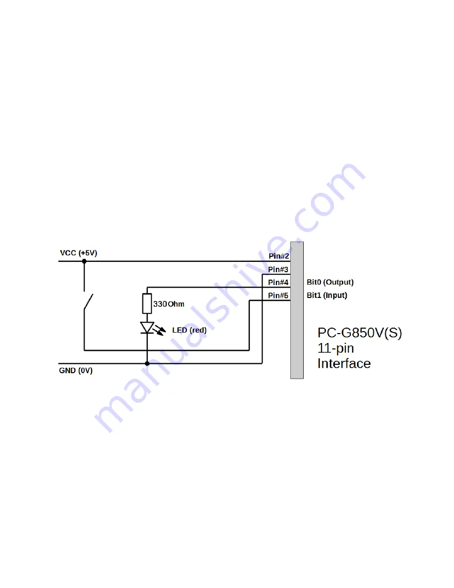
In order to demonstrate the PIO-mode usage, here is a very simple example:
In this example bit-0/pin-4 is an output, which lights up an LED when it is in the HIGH
(logic 1) state. Bit-1/pin-5 on the other hand serves as an input that represents the state
of a push button switch. An open input (i.e. undefined level) is internally pulled down and
thus interpreted as logic 0. This is the case, if the push button is open. In order to
distinguish that state from the closed state, the push button is connected to VCC (i.e.
HIGH/logic 1) on the other side and not to GND.
Let the goal of the “microcontroller”-code be to switch on the LED by the first button-click
and to switch it off again by the next button-click (and so on). Let us use the
programming language C for this example – BASIC would be similar, but less structured.


