Sharp MX-4140N Скачать руководство пользователя страница 6

MX-5141FN  MX-4140N/4141N/5140N/5141N (MAIN UNIT)  2 – 2

2.  Installation

Note before installation

* When connecting the main unit with the optional STAND/1 X 500

SHEET  PAPER  DRAWER  or  STAND/2  X  500  SHEET  PAPER
DRAWER,  first  unpack  and  install  the  PAPER  DRAWER  then
unpack  the  main  unit  and  securely  place  the  main  unit  on  the
PAPER DRAWER before installing the main unit.
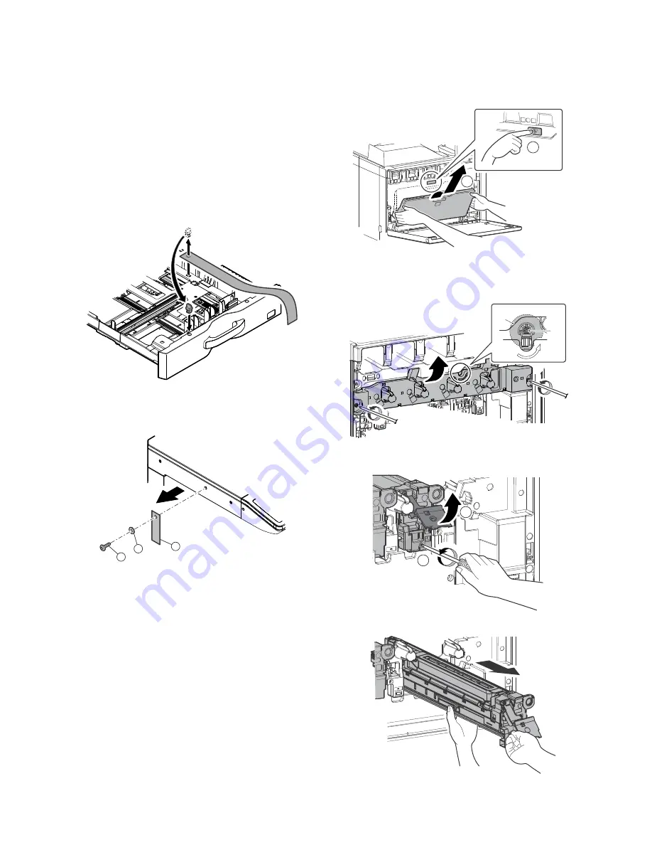
A. Lock release

(1)

Tray rotation plate lock release

1)

Pull  out  the  tray.  Turn  the  fixing  material  and  remove  it.
Remove the caution label. 
Attach the removed fixing material to the position shown in the
figure for future use. 
Close the tray which was pulled out.

(2)

Scanner (2/3 mirror unit) lock release

1)

Remove  the  optical  unit  fixing  screw,  and  remove  the  note
label.

B. Developing (each color) installation

Be careful not to attach fingerprints or oily dirt on the DV roller sur-
face.

1)

Open the front cabinet, and remove the waste toner box.

2)

Check that the lock is released as shown in (A).

Loosen the blue screw, and open the drum positioning unit.

* When the lock is not released, use a screwdriver to turn the

screw (B) counterclockwise so that it is fit as (A).

3)

Open  the  DV  lock  lever,  and  release  the  fixing  screw.
(1position for each color)

4)

Pinch the knob and remove the development unit.

2

1

3

2

1

A

B

1

2

Содержание MX-4140N

Страница 1: ...ce these parts with specified ones for maintaining the safety and performance of the set SHARP CORPORATION This document has been published to be used for after sales service only The contents are subject to change without notice MX 4140N 5140N MX 4141N 5141N MODEL DIGITAL FULL COLOR MULTIFUNCTIONAL SYSTEM ...

Страница 2: ...e of a step up transformer is also available In this case the capacity must be great enough for the max power consumption of the machine 3 Power frequency waveform The frequency must be within the range of the specified frequency 2 If power waveform is deformed a trouble may occur 4 Safety Be sure to properly ground the machine Grounding earth connection must be performed before inserting the powe...

Страница 3: ...ty may be adversely affected and a trouble may be caused There was a trouble in a place where silicon series gas or volatile components are generated Use great care for avoiding this 5 Vibration Avoid installation near a machine which produces vibrations If vibrations are applied to the copier machine copy images may be deflected and a trouble may be caused F Note for handling PWB and electronic p...

Страница 4: ...erial on the developing unit Fusing unit Be careful not to leave fingerprints oil grease or other foreign material on the fusing roller and the external heating belt Do not leave the fusing roller in contact state for a long time If these items are neglected a trouble may be generated in the copy and print image quality 2 Transit and delivery A Implements facility and manpower It is recommendable ...

Страница 5: ...T 1 Unpacking A Unpacking procedure 1 Remove the PP band 2 Remove the internal packing pads with the machine B Removal of the fixing tape and protection material C Packed items check 1 North America only DSPF model RSPF model No Name Quantity 1 Developer 1 4 2 Operation manual 1 3 Operation manual pocket 1 1 1 2 3 ...

Страница 6: ...erial to the position shown in the figure for future use Close the tray which was pulled out 2 Scanner 2 3 mirror unit lock release 1 Remove the optical unit fixing screw and remove the note label B Developing each color installation Be careful not to attach fingerprints or oily dirt on the DV roller sur face 1 Open the front cabinet and remove the waste toner box 2 Check that the lock is released...

Страница 7: ...er stir ring toner and developer in the bag supply it to the develop ing unit When replacing developer use an extreme care not to drop developer on the drive section marked with 8 Install the DV cover in the arrow direction A When installing the DV cover be sure to engage the pawl with the boss 9 Secure the DV cover with the two screws 10 Shake the developer unit horizontally a few times When supp...

Страница 8: ...ts stores in memory the average sensor detection level as the control level for the ref erence toner density Operating times approx 3 minutes MEMO Be sure to select all of the four colors K C M Y 6 After the machine completes cycling exit the simulation mode by pressing the CA key on the main unit D Installation of individual color toner cartridges The life of each toner cartridge is as follows Bl...

Страница 9: ...ositions 3 Insert the cartridge securely until it locks Push it until the click sound is heard E Cleaning of LSU s dust proof glass Dust from the transfer belt or shutter or some other adjacent part may fall onto the LSU during transport or installation Be sure to clean the dust proof glass before checking the image quality 1 Open the front cabinet and remove the waste toner box 2 Detach the LSU c...

Страница 10: ...omer s request To customize the following items after completion of the destination setup change the set values I Image quality check 1 Image loss void area image off center check Make a copy in the original table mode and in the RSPF DSPF mode Check to confirm that the image loss and the void area are in the range shown below Item Description Type Select the type of paper that is loaded in the tr...

Страница 11: ... is completed EXECUTE key returns to the normal display and the value of the adjustment result is displayed The current skew level for each color is displayed on the SKEW display section No Item SIM 1 Print engine image distortion adjustment Manual adjustment OPC drum phase adjustment Automatic adjustment Color registration adjustment Automatic adjustment 50 22 2 Copy color balance and density che...

Страница 12: ...e section and the process sec tion Display Item Content Display Default NOTE MAIN F C Registration adjustment value main scanning direction Cyan laser writing position F side 1 0 199 0 100 M Registration adjustment value main scanning direction Magenta laser writing position F side 1 0 199 0 100 Y Registration adjustment value main scanning direction Yellow laser writing position F side 1 0 199 0 ...

Страница 13: ...d paper for color b Note for checking the monochrome copy mode density To check the density use the gray test chart UKOG 0162FCZZ Set the copy density level to Manual 3 in the Text Printed Photo mode Manual In addition all the color balance adjustments in the user adjust ment mode must be set to the default center Check with the gray test chart UKOG 0162FCZZ In the copy density check with the gray...

Страница 14: ...istrations one point for the main scanning and one point for the sub scanning are not shifted 3 The resolution of 5 0 5 points can be seen 4 The color difference in gray balance between the F and the R sides is not so great 5 There are no white and black streaks 6 Color texts are clearly reproduced 7 The background density is not so light ...

Страница 15: ...nfirm the following 1 There are 12 void areas 2 The resolution of 4 0 5 points can be seen 3 The density difference between the F and the R sides is not so great 4 There are no white and black streaks 5 The background density is not so light 6 The black low density gradation is copied slightly ...

Страница 16: ... darker level The density changing direction must not be reversed The density level of each color must be almost at the same level Method 2 When the PCL or the PS printer function is not provided GDI model use this method for check Use SIM 67 25 to print the color balance adjustment sheet and compare each process CMY black patch color balance and the black patch to check the color balance The prin...

Страница 17: ...the color balance is registered with SIM63 7 as the service target if the color balance is required to be adjusted select the SERVICE target The copy color balance adjustment is automatically executed and prints the color balance check patch image If there is any streak or unclear print on the printed check pat tern check the print engine for any problems 5 Press EXECUTE key The printer color patc...

Страница 18: ...nt step 1 is automatically performed and the color balance check patch image is printed out If there is any streak or unclear print on the printed check pat tern check the print engine for any problems 8 The initial setting menu of the half tone image correction is dis played Press OK key The initial setting of the half tone image correction is per formed 9 Wait until EXECUTE key is displayed When...

Страница 19: ...e automatic adjustment and a satisfactory result is not obtained perform the manual color balance adjustment ADJ 10C 2 12 Check the printer color balance and density Refer to the item of the printer color balance and density check When satisfactory color balance and density are not obtained from the automatic adjustment by selecting the factory target in procedure 7 change the factory color balanc...

Отзывы: