background image

– 28 –

MD-SR50H/50W/60E/60W
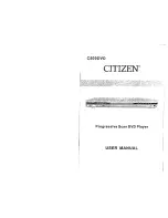
• The numbers   

1

   to   

18

  are waveform numbers shown in page 31.

       : Through-hole where the top, bottom and +B patterns are connected.
       : Through-hole where the top, bottom and hround patterns are connected.
       : Through-hole where the top and bottom patterns are connected.

A

B

C

D

E

F

G

H

1

2

3

4

5

6

Figure 28 WIRING OF P.W.BOARD (1/3)

R291

HOLD
SW402

IC257 

R292

TP803 

TP171 

TP106 

C291

TP441 

C454

R464

TP100 

L171

C171

C172

CK112 

C110

C109

C112

C111

C106

C107

TP105 

TP144 

TP110 

TP139 

TP118 

TP103 

TP101 

C161

TP114 

R106

Q101

CK105 

IC101 

C102

CK101 

CK107 

R154

C103

R408

TP109 

C104

R407

TP111 

CN101 

R105

TP102 

TP116 

TP404 

CK106 

CK104 

CK102 

TP115 

C130

CK103 

TP151 

TP117 

R422

TP145 

TP108 

TP119 

CK108 

TP133 

TP121 

TP130 

TP131 

TP132 

TP122 

TP120 

TP205 

R101

R102

R103 R104

CK901 

TP351 

C121

C122 C123

C124

R920

R412

TP409 

TP665 

TP407 

TP201 

R411

IC351 

R413

C357

TP658 

R414

IC402 

TP408 

TP410 

TP411 

R415

TP655 

TP659 

R416

TP601 

R404

R406

R405

TP405 

TP652 

R403

TP651 

TP406 

TP660 

TP653 

C604

C603

L604

L603

TP661 

C609

R921

TP657 

TP610 

CN601 

R922

L609

TP654 

C836

IC873 

IC601 

L610

C622

TP666 

C610

TP662 

TP663 

TP664 

C837

TP602 

C651

R600

TP708 

EJECT
SW401 

L710

C715

Q711

TP707 

TP706 

C734

C733

R728

R717

C704

C731

R701

TP202 

R718

C505

C506

R727

TP702 

C703

R703

TP703 

C713

TP713 

R502

C502

IC701 

TP701 

TP704 

R715

IC501 

TP714 

C501

R713

R716

TP712 

R501

R714

TP705 

R729

TP500 

C721

TP711 

R730

L500

C722

TP727 

TP728 

TP729 

TP721 

L800

TP722 

TP805 

D801

TP772 

TP725 

TP726 

TP723 

R492

TP801 

TP802 

C492

TP771 

IC703 

R765

D494

R767

R762

R768

C491

TP724 

R766

D495

D496

L801

R808

R810

C765

C766

C758

D492 L491

C481

C760

R757

R758

R754

R761

TP453 

R457

TP412 

TP451 

TP452 

R456

TP481 

TP454 

R458

R455

TP482 

TP456 

C482

CN482 

CN451 

TP483 

TP460 

TP486 

TP458 

TP461 

TP487 

TP489 

TP463 

TP459 

TP488 

R451

R452

R453

R454

TP462 

TP206 

TP656 

R463

TP457 

R806

TP455 

TP419 

R465

D803

TP210 

R461

Q891

TP209 

R466

R811

TP417 

R802

D431

TP416 

TP208 

D802

R801

R809

R803

C431

TP204 

R431

IC431 

R853

IC852 

TP403 

TP400 

IC401 

C857

C860

C856

R854

TP401 

C825

XL401 

R855

R856

R402

D822

TP414 

C830

R831

TP413 

C876

R823

C828

IC822 

C401

R832

TP415 

TP212 

R871

C839

C827

TP203 

TP402 

C826

IC871 

R826

R443

R423

R425

R424

C206

TP207 

D823

C259

TP804 

C200

TP200 

R287

R269

R283

R819 R277

IC809 

R261

R262

R263

R266

R267

TP809 

Q257

R284

IC259 

R279

R271

R270

C255

IC256 

IC258 

IC253 

IC260 

TP842 

R288

R281

R286

C254

R250

R272

R256

R255

R257

R285

R282

Q251

D281

R252

IC255 

IC251 

R253

R251

R293

Q250

TP841 

D251

C251

C253

R254

C252

R295

R294

R296

IC892 

R827

R824

R825

R857

D461

C714

1

5

10

15

20

25

30

35 40

45

50

55

60

65

70

80

85

90

95

PWB-A(TOP VIEW)

1

4

5

8

5

8

1

4

1

1

1

1

1

1

1

1

1

3

3

3

3

3

4

4

4

4

4

4

4

4

6

6

6

6

1

3

4

6

1

3

4

6

5

5

5

8

8

3

2

100

75

76

26

1

2

3

J801
DC IN

J703

REMOTECONTROL/

HEADPHONES

1

1

2

3

3

4

1

1

1

5

5

10

12

1

5

10

12

13

15

20

24

13

15

20

24

8

9

10

15

16

8

7

2

1

6

5

3

4

13

1

9

1

1

5

10

12

15

20

13

24

25

30

35

36

40

37

45

48

1

5

10

12

15

20

13

24

25

30

35

36

40

37

45

48

1

22

7

5

5

1

1

4

8

8

10

14

1

16

4

5

TO MECHANISM
FLEXIBLE PWB
ASS'Y
P30 6-C

TO  OPTICAL
PICKUP UNIT
P30 1-D

BATTERY
TE

BATTERY
TERMINAL,-

51

6

3

4

2

3

9

13

15

18

5

7

8

6

1

14

11

10

TO LCD

ASS'Y

P30 5-E

TO KEY

FLEXIBLE

PWB ASS'Y

P30 3-E

17

16

3

4

2

J702
MIC IN

Содержание MD-SR505E

Страница 1: ...IT 31 TROUBLESHOOTING 32 FUNCTION TABLE OF IC 35 PARTS GUIDE EXPLODED VIEW PACKING METHOD MD SR50H for U K SR60E Only SERVICE MANUAL SHARP CORPORATION No S2006MDSR50H This document has been published to be used for after sales service only The contents are subject to change without notice MD SR50H BL MD SR50H S MD SR50H YR MD SR50W BL MD SR50W S MD SR60E GL MD SR60W S In the interests of user safe...

Страница 2: ...airing If the AC adaptor or batteries are connected when the top houising disc cover of the unit is removed and the PLAY key is pressed the laser will light up during focus access 2 3 seconds Fig 2 1 During the operation the laser will leak from the opening between the magnetic head and the mechanical chassis Fig 2 2 In order to protect your eyes you must not look at the laser during repair Before...

Страница 3: ... 240V 50 60 Hz DC 1 5V Commercially available AA size LR6 alkaline battery x 1 DC 4 5V Separately available car adaptor AD CA20X for cars with a 12 24V DC negative earth electrical system Power source DC 1 2V Rechargeable Nickel Metal Hydride MD SR60W battery AD N70BT x 1 DC 5V AC adaptor AC 220V 50 Hz DC 1 5V Commercially available AA size LR6 alkaline battery x 1 DC 4 5V Separately available car...

Страница 4: ...to Mark Time Mark Button 24 Mode Button 25 Bass Delete Button 26 Fast Reverse Recording Level Down Name Select Button 27 Fast Forward Recording Level Up Name Select Button 28 Enter Fast Play Synchro Button 29 Earphones Line Output Socket 30 Optical Line Input Socket 31 Microphone Input Socket 32 Open Lever 33 5V DC Input Socket 34 Battery Cover 35 Hold Switch Remote control unit 1 Headphones Socke...

Страница 5: ...er than normal The battery life will recover with normal use i e charg ing and discharging To avoid shortening the service life of the battery only recharge the battery after it has been completely discharged RECORDING USING THE OPTICAL DIGITAL CABLE This is the method used for recording digi tal signals from CDs or MDs exactly as they are stored on the original Compared to re cordings made from a...

Страница 6: ...y after turning on a heater When the unit is placed in a room where there is excessive steam or moisture When the unit is moved from a cool place to a warm place When the unit has condensation inside the disc signals cannot be read and the unit may not function properly If this happens remove the disc The condensation should evaporate in approximately 1 hour The unit will then function properly Ma...

Страница 7: ... tracks may not be combined in editing The total of the recorded time and time remaining on a disc may not add up to the maximum possible recording time When recorded tracks are played back using the cue and review op erations some sounds may be skipped A track number can be created in the middle of a track ERROR MESSAGES Error messages Remedy Meaning BLANK MD BATT EMPTY The battery is run down Ch...

Страница 8: ... Since the screws are small incorrect fixing may result in malfunction 3 When repairing pay utmost attention to static electricity of IC REMOVAL PROCEDURE STEP FIGURE Figu re 8 1 Figure 8 2 Figure 8 3 Caution Carefully handle the main PWB and flexible PWB After removing the flexible PWB 1 for the optical pickup from the connector do not touch directly the front end of flexible PWB with your hand s...

Страница 9: ...f head up down motor lead wire 2 Remove the screw B2 x 1 pc and remove the flexible PWB 3 Remove the screw B3 x 1 pc and remove the head up down motor Note Take care so that the motor gear is not damaged If the gear is damaged noise is caused How to remove the sled motor See Fig 9 3 1 Remove the stop washer C1 x 1 pc and remove the drive gear C2 x 1 pc 2 Remove the screws C3 x 2 pcs and remove the...

Страница 10: ...ine 10 lines or 384 lines manual jump is performed C1 error rate display pit section ADIP error rate display groove section The temperature correction is performed only when servo start is performed but the posture correction is not performed during continuous playback 4 TEST REC Mode Continuous record from the specified address is performed Change of record laser output servo gain is also changed...

Страница 11: ...ng changes continuously one cycle being 100 ms When the BASS button is pressed in the continuous playback mode the number of jump lines changes as follows 1 10 384 1 After the number of jump lines is indicated for one second the address indication is restored T R _ When the SKIP UP button is pressed in the continuous playback mode the specified number of lines is jumped in the FWD direction When t...

Страница 12: ...ed in the memory When the DISP button is pressed while the error data indication menu appears the error data is initialized C L E A R _ Error Code Explanation of error history code 12h RF side FG TG and TCRS adjustment termination failure 13h Adjustment servo retraction excessive retrial 16h C IN detection time over 17h A B E F and TCRSO offset measurement value out of tolerable range 21h Focus re...

Страница 13: ... or set PLAY ON in standby state 2 Start the EEPROM mode Temp menu Key operation in order of BASS SKIP DOWN x 2 times PLAY PLAY in the test mode STOP state TM is displayed Temperature code Temperature reference 3 Once press SKIP UP and determine the displayed microcomputer TEMP input AD value TPin is displayed TEMP input AD value 4 At the ambient temperature determine the temperature corrected val...

Страница 14: ... H C T 1 _ 1 1 H C T 2 _ 4 0 H C T 3 _ 3 0 H R C 0 _ C 0 H R C 1 _ F E H S Y C _ A 6 H P W L _ 0 1 H D R 1 _ 0 0 H D R 2 _ 0 0 H I N 1 _ C 9 H I N 2 _ 6 4 H I N 3 _ 9 9 H I N H _ 6 4 H D R H _ 0 C H P L E _ 1 B H R C E _ 4 2 H E L T _ 7 6 H S L T _ 4 5 H S P M _ 0 0 H M S L _ 0 0 H U S 0 _ 0 0 H U S 1 _ 0 0 H U S 2 _ 0 0 H Item display Set values F G _ _ B 0 H F F 1 _ 7 0 H F F 2 _ E 8 H F Z H _ E...

Страница 15: ...enu M A N U 1 ATT manual adjustment menu M A N U 2 Error history display menu E D A T A Test mode normal playback menu N O R M A L Preautomatic Adjustment menu Preadjustment error adjustment value output During preadjustment adjustment Adjustment error Normal end Preadjustment normal end adjustment value output During ATT automatic adjustment PLAY PLAY A U T O 1 Preautomatic Adjustment A D J O K A...

Страница 16: ...he start address changes as follows when the DISP button is pressed 0 0 3 2 H initial value 0 3 C 0 H 0 7 0 0 H 0 8 A 0 H A d 0 0 3 2 A d 0 3 C 0 DISP DISP A d 0 7 0 0 DISP DISP A d 0 8 A 0 In the start address setting state the start address change digit changes when the BASS button is pressed 1st digit initial value 2nd digit 3rd digit A d 0 0 3 2 A d 0 0 3 2 MODE MODE A d 0 0 3 2 MODE In the co...

Страница 17: ...S Q When the STOP button is pressed in specific menu the TEST MODE STOP state is set TEST mode normal playback menu Continuous playback Mode and address display PLAY N O R M A L Test Mode Normal Playback When the STOP button is pressed in specific menu the TEST MODE STOP state is set When the NORMAL mode is canceled the power is turned off Error history display menu Error history 0 display Error c...

Страница 18: ...ecific menu the TEST MODE STOP state is set When the DISP button operation is performed in the specific state the menu changes to TEMP SETTING menu In the specific state the setting changes in the range of 00h to FFh when the VOL UP DOWN button is pressed The upper limit varies depending on the items When the MODE button is pressed in each state the set digit is changed Focus setting menu PLAY F o...

Страница 19: ...each state the set digit is changed Tracking setting menu PLAY T r a c k Tracking Setting T G T F 1 SKIP UP SKIP DOWN T F 2 SKIP UP SKIP DOWN T F S SKIP UP SKIP DOWN T B o SKIP UP SKIP DOWN T B t SKIP UP SKIP DOWN T K o SKIP UP SKIP DOWN T K t SKIP UP SKIP DOWN T D o SKIP UP SKIP DOWN T D t SKIP UP SKIP DOWN When the STOP button is pressed in specific menu the TEST MODE STOP state is set When the ...

Страница 20: ... n SKIP UP SKIP DOWN When the STOP button is pressed in specific menu the TEST MODE STOP state is set When the DISP button operation is performed in the specific state the menu changes to TEMP SETTING menu In the specific state the setting changes in the range of 00h to FFh when the VOL UP DOWN button is pressed When the MODE button is pressed in each state the set digit is changed Adjustment sett...

Страница 21: ...In the specific setting display state the setting change digit changes when the P MODE button is pressed 1st digit initial value 2nd digit P MODE P MODE In the specific state the setting changes in the range of 0h to Fh when the VOL UP DOWN button is pressed When the MODE button is pressed in each state the set digit is changed Control setting menu PLAY C T R L Control Setting C T 0 C T 1 SKIP UP ...

Страница 22: ...e STOP button is pressed in specific menu the TEST MODE STOP state is set When the DISP button operation is performed in the specific state the menu changes to TEMP SETTING menu In the specific setting display state the setting change digit changes when the P MODE button is pressed 1st digit initial value 2nd digit P MODE P MODE In the specific state the setting changes in the range of 0h to Fh wh...

Страница 23: ...symbol is microfarad As to electro lytic capacitor the expression capacitance withstand volt age is used CH TH RH UJ Temperature compensation ML Mylar type The indicated voltage in each section is the one measured by Digital Multimeter between such a section and the chas sis with no signal given Parts marked with are important for maintaining the safety of the set Be sure to replace these parts wi...

Страница 24: ...0V 2 5V 2 34V 0V 2 5V 0V 1 26V 0V 2 35V 0V 0V 2 5V 0V 2 34V 2 34V 0V 0V 0V 0V 0V 0V 2 74V 2 74V 2 5V 0V 2V 4 44V 0 45V 1 03V 3 28V 0 45V 0 99V 4 38V 4 4V 4 46V 0V 0V 5 36V 0V 0V 0V 2 35V 5 36V 1 17V 2 8V 0 37V 0V 1 17V 1 17V 1 16V 1 26V 2 8V 2 06V 2 06V 0V PIN NO VOLTAGE 1 IC842 2 4 5 3 2 81V 2 56V 0V 2 36V PIN NO VOLTAGE IC852 1 2 4 5 6 7 8 3 1 17V 2 8V 0 67V 0V 1 2V 1 17V 1 16V 1 26V 1V 2 36V 0V...

Страница 25: ...Y IC901 SPINDLE MOTOR DRIVER LB1971V IC703 AUDIO AMP IR3R59N IC701 AUDIO AMP IR3R54N IC601 4 CH PWM DRIVER LV8017W VM IC402 EEPROM 58X2402T VS IC202 IX2567AF 4M D RAM 2 5V OPTICAL IN UNIT J701 OPTICAL IN J701 LINE IN J702 MIC IN READY FOR PLUG IN POWER 2 0V REGULATOR IC203 62FP2002 1 2 21 23 6 5 7 7 30 35 VCC VG 43 16 18 20 22 39 41 17 21 27 40 44 13 14 23 40 26 29 32 37 39 46 1 9 11 19 7 9 66 74 ...

Страница 26: ...2 VSS VSS VCC uSTBY NMI EXTAL WDTOVF MD2 MD1 MD0 RCPCNT BUZOUT VSS VSS VSS EEPD PCNT1 PBOPON RCLAT PBLAT RADAT RACLK RFLAT RMDAT MCMON CKSTP INPGCK PDCNT INPGI MCPGI TEST1 TEST0 KHOLD REC PLAY DCEXT DSPSCK DSPSTB DSPDAT HDON DISCPR DCNT1 RKEY EJSW AVCC FOK SENSE RESET CIN SPIN XTAL VCC EMPH0 LDON INNSW VSS SYRD SYRS SYWR SYD7 SYD5 SYD4 SYD6 SYD3 SYD1 SYD2 SYD0 XRST EEPK AVSS EPCS Vref LDVAR TEMP H...

Страница 27: ...H R713 10K C726 3 3 10 R725 100 R726 39K Q721 2SD1979S C725 3 3 10 L702 L703 R714 10K L704 J701 OPTICAL LINE IN J702 MIC IN C722 3 3 10 R724 6 8K R723 6 8K C724 0 001 C723 0 001 C721 3 3 10 C731 0 22 R727 8 2K R728 1K R729 2 7K R730 2 7K J703 REMOTECONTROL HEADPHONES C491 0 1 D494 MA8075M L491 33 R492 1K D492 MA8075M C492 1 D496 MA8075M D495 MA8075M R768 4 7 R767 4 7 C766 0 22 C765 0 22 R766 15 R7...

Страница 28: ...D494 R767 R762 R768 C491 TP724 R766 D495 D496 L801 R808 R810 C765 C766 C758 D492 L491 C481 C760 R757 R758 R754 R761 TP453 R457 TP412 TP451 TP452 R456 TP481 TP454 R458 R455 TP482 TP456 C482 CN482 CN451 TP483 TP460 TP486 TP458 TP461 TP487 TP489 TP463 TP459 TP488 R451 R452R453 R454 TP462 TP206 TP656 R463 TP457 R806 TP455 TP419 R465 D803 TP210 R461 Q891 TP209 R466 R811 TP417 R802 D431 TP416 TP208 D802...

Страница 29: ... C846 C847 C841 F841 D842 SW403 LID DETECTION R850 C845 R844 C818 R818 C850 4 1 2 3 C202 L841 C833 IC841 D831 C835 D832 R202 D841 C843 C842 C821 L821 C834 C838 R833 C832 C201 L200 IC821 CK222 IC203 CK224 D821 C822 C212 R222 C852 C211 XL201 C851 CK207 D851 L851 L862 C869 IC851 C868 C863 CK203 D861 C862 CK204 CK202 CK201 C840 Q461 D862 C209 R462 R460 IC621 C606 R621 C823 R622 D622 R816 R815 R814 Q80...

Страница 30: ...netic Head Flexible PWB 23 Magnetic Head 21 Mechanism Flexible PWB 8 M902 Sled Motor PH901 Photo Interrupter M901 Spindle Motor SW902 Disc Protect To Main PWB CN601 To MAIN PWB P28 6 F CN482 LCD Ass y 214 Key Switch Flexible PWB Ass y 213 CN451 CN101 To MAIN PWB P28 1 C P28 1 E To MAIN PWB P28 6 E M903 Lift Motor ...

Страница 31: ...CH1 0 000V CH2 0 00V Main 1K Zoom 1K CH3 0 00V CH4 0 00V Trigger Mode AUTO Type EDGE CH1 Detay 0 0ns Hold OFF MINIMUM T TP201 EFMMON Stopped CH1 2V DC 10 1 500ms div 500ms div 1 MORM 200MS s 9 1994 12 15 08 57 26 Filter Offset Record Length Smoothiing OFF BW FULL CH1 0 00V CH2 0 00V Main 10K Zoom 10K CH3 0 000V CH4 0 0V Trigger Mode NORMAL Type EDGE CH1 Detay 0 0ns Hold OFF MINIMUM T TP201 EFMMON ...

Страница 32: ...ently clean the lens with a lens cleaning tissue and a small amount of isopropyl alcohol Do not touch the lens with the bare hand Is the power supply turned on when the remote control button or main unit button is pressed No Perform the check stated in item Power is not turned on when the PLAY button is pressed Perform the check stated in item Abnormal display No Yes Does the display operate norma...

Страница 33: ...ck time display advance Yes Position check in INNER mode Check IC201 and IC202 connection line Is the lead in photointerrupter set to OFF when the optical pickup moves to the innermost periphery in NORMAL mode Is TP654 in H level Check the lead in photointerrupter mechanical flex PWB soldering and CN601 connection No Ia an attempt to repeat repeatedly the TOC part performed on the low reflection d...

Страница 34: ...Check for soldering failure of IC201 No Check periphery of IC401 and IC101 Check whether there is any damage in IC101 periphery of laser diode Yes Check for defects of IC351 in head drive flexible PWB head flexible PWB No Yes Is audio monitor output given in normal mode LINE IN record Check waveforms of pins 8 10 11 12 of IC501 pins 70 to 73 of IC201 Is waveform obtained on IC501 pins 2 and 3 No Y...

Страница 35: ... 32 PC0 CKSTP Output Microcomputer stand by operation monitor 33 PC1 _XRST Output System LSI hand reset output 34 PC2 SENSE Input System LSI servo sense input 35 PC3 _FOK Input Focus OK signal input 36 PC4 RCLAT Output Record audio IC data latch output 37 PC5 TEST1 Input Test mode setting input 1 38 PC6 TEST0 Input Test mode setting input 0 39 PC7 EMPH0 Output Audio emphasis control output 0 40 Vc...

Страница 36: ...t Battery voltage detection input 80 AN1 PLCHK Input Power supply circuit abnormal detection input 81 AN2 HKEY2 Input Unit key operation detection input 2 82 AN3 HKEY1 Input Unit key operation detection input 1 83 AN4 RKEY Input Remote control key operation detection 84 AN5 TEMP Input Ambient temperature detection inputinput 85 AN6 CHGCNT Output Charging current control output 86 DA1 LDVAR Output ...

Страница 37: ...8 EXPORT6 DAPON Output D A converter operation control output H Operation ON 59 EXPORT7 ADPON Output A D converter operation control output H Operation ON System LSI expansion output port 6th generation LR37811 Pin No Function Port Name Terminal Name Input Output Remarks H H Normal mode H L No adjustment mode L H Test mode L L Settings prohibited TEST1 Details 1 List of TEST port settings H H fs 3...

Страница 38: ... 38 MD SR50H 50W 60E 60W M E M O ...

Страница 39: ...pacitors VCC Ceramic type VCK Ceramic type VCT Semiconductor type VC MF Cylindrical type without lead wire VC MN Cylindrical type without lead wire VC TV Square type without lead wire VC TQ Square type without lead wire VC CY Square type without lead wire VC CZ Square type without lead wire VC J The 13th character represents capacity difference J 5 K 10 M 20 N 30 C 0 25 pF D 0 5 pF Z 80 20 If ther...

Страница 40: ...31 832 VHDHRB0103B 1 J AC Schottky HRB0103B D841 VHDF10J2E 1 J AC Schottky F10J2E D842 VHDHRB0103B 1 J AC Schottky HRB0103B D851 VHDD1FH3 1 J AE Schottky D1FH3 D861 862 VHDF10J2E 1 J AC Schottky F10J2E PH901 8 2 VHPGP1S93K 1 J AF Photo Interrupter COILS L100 VPBNN100K0000 J AC 10 µH L171 RCILC0356AFZZ J AC 10 µH L491 VRS TV2AB330J J AA 33 ohms 1 10W L500 RCILC0344AFZZ J AC 47 µH Choke L601 604 RCI...

Страница 41: ...1JB154D J AA 150 kohms 1 16W R253 VRS CY1JB393D J AA 39 kohms 1 16W R254 VRS CY1JB223J J AA 22 kohms 1 16W R255 VRS CY1JB472J J AA 4 7 kohms 1 16W R256 VRS CY1JB563J J AA 56 kohms 1 16W R257 VRS CY1JB273D J AA 27 kohms 1 16W R261 VRS CY1JB102J J AA 1 kohm 1 16W R262 263 VRS CY1JB683D J AA 68 kohms 1 16W R266 VRS CY1JB563D J AA 56 kohms 1 16W R267 VRS CY1JB103D J AA 10 kohm 1 16W R269 VRS CY1JB303D...

Страница 42: ...ing Eject Lever 19 MLEVF2637AFM1 J AH Lift Working Lever Ass y 20 MLEVF2640AFZZ J Lever Lift 21 RCILH0002AWZZ J Magnetic Head 22 PCOVP1339AFZZ J AD Cover Mechanism 23 QPWBH0338AFZZ J AH Magnetic Head Flexible PWB 24 MLEVF2639AFFW J AD Lever Lift Joint 25 MLEVF2638AFFW J AD Lever Block 26 MSPRD1362AFFJ J AD Spring Lift Lever 501 LX BZ0800AFZZ J AA Screw ø1 4 2 5mm 502 LX BZ0804AFFF J AA Screw ø1 4 ...

Страница 43: ...AWZZ J Operation Manual SR50W for Australia New Zealand 10 TINSZ0519AWZZ J Operation Manual SR60W 10 TINSZ0520AWZZ J Operation Manual SR50H for Europe 10 TINSZ0521AWZZ J Operation Manual SR50W Except for Australia New Zealand 11 SPAKZ0490AWZZ J AC Operation Manual Spacer SR60W SR60E SR50H for U K Only 12 UBAGC0006AWSA J Carrying Case 13 SPAKC0944AWZZ J Packing Case SR60W 13 SPAKC0945AWZZ J Packing...

Страница 44: ... E F G H 1 2 3 4 5 6 Figure 5 MD MECHANISM EXPLODED VIEW 5 M903 M902 M901 503x2 505x3 508x2 502x2 3 501 21 23 511 8 3 SW902 8 1 8 8 2 PH901 504 503 504 12 19 11 1 2 16 17 15 509 510 24 506 13 503 14 5 22 26 9 18 20 25 6 7 512 507 ...

Страница 45: ...BINET EXPLODED VIEW 6 204 242 MD MECHANISM 210 205 203 214 234 233 213 215 202 237 601x2 601 x2 216 217 603 602 211 212 218 236 601x2 601 601 601x2 209 PWB A 208 220 220 221 219 229 223 222 207 224 225x2 240 226 201 241 241 235 605x4 228 227 231 232 206 230 601 ...

Страница 46: ...AKZ0599AWZZ Pad AC Adapter 7 RADPA8046AWZZ AC Adapter 8 QCNWG0382AFZZ Connecting Cord RCA Type 9 SPAKA0237AWZZ Packing Add 10 TINSE0289AWZZ Operation Manual SR60E 10 TINSE0290AWZZ Operation Manual SR50H for U K 11 SPAKZ0490AWZZ Operation Manual Spacer 12 UBAGC0006AWSA Carrying Case 13 SPAKC0945AWZZ Packing Case SR60E 13 SPAKC0970AWZZ Packing Case SR50H S for U K 13 SPAKC0971AWZZ Packing Case SR50H...

Страница 47: ...MD SR50H 50W 60E 60W M E M O 8 ...

Страница 48: ...rieval system or transmitted in any from or by any means electronic mechanical photocopying recording or otherwise without prior written permission of the publisher A0002 4543NS HA M SG SK SCA SCNZ EX SHARP CORPORATION Communication Systems Group Quality Reliability Control Center Higashihiroshima Hiroshima 739 0192 Japan Printed in Japan ...

Отзывы: