background image

17 

US

Connection

and Installation

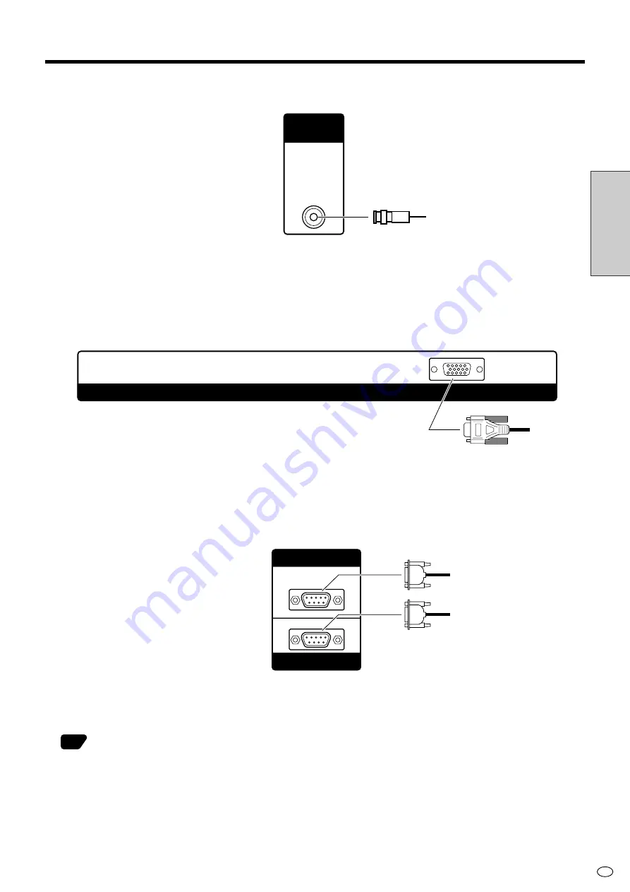
VIDEO OUTPUT

When INPUT2 is displayed, video from INPUT2 is output. Otherwise video from INPUT1 is output.

INPUT3/PC (ANALOG) OUTPUT

When INPUT3 is displayed, video from INPUT3 is output. Otherwise PC (analog) video is output.

RS-232C INPUT/RS-232C OUTPUT

The RS-232C INPUT and RS-232C OUTPUT are used to control this monitor with a PC.
To connect a single monitor to a PC, connect to the RS-232C INPUT terminal.
To connect multiple monitors in a daisy chain for control by PC, use the RS-232C OUTPUT terminal.

37

RS-232C INPUT

RS-232C OUTPUT

INPUT 3 / PC (ANALOG) OUTPUT

VIDEO

OUTPUT

Video

Connecting Peripheral Equipment (Continued)

Содержание LC-M3700

Страница 1: ...en 100 de papel reciclado de postconsumo INPUT RETURN MENU STANDBY ON ENLARGE WIDE LCD MONITOR ENTER VOL LC M3700 LC M3710 OPERATION MANUAL BEDIENUNGSANLEITUNG MODE D EMPLOI MANUAL DE MANEJO WIDE LCD MONITOR BREITBILD LCD MONITOR MONITEUR GRAND ÉCRAN À CRISTAUX LIQUIDES MONITOR LCD PANORÁMICO ENGLISH DEUTSCH FRANÇAIS ESPAÑOL OPERATION MANUAL MODE D EMPLOI BEDIENUNGSANLEITUNG MANUAL DE MANEJO LC M3...

Страница 2: ...us voltage within the product s enclosure that may be of sufficient magnitude to constitute a risk of electric shock to persons The exclamation point within a triangle is intended to alert the user to the presence of important operating and maintenance servicing instructions in the literature accompanying the product WARNING TO REDUCE THE RISK OF FIRE OR ELECTRIC SHOCK DO NOT EXPOSE THIS PRODUCT T...

Страница 3: ... interference by one or more of the following measures Relocate or adjust the receiving antenna Increase the separation between the equipment and receiver Connect the equipment into an outlet on a circuit different from that to which the receiver is connected Consult the dealer or an experienced radio TV technician for help WARNING FCC Regulations state that any unauthorized changes or modificatio...

Страница 4: ... table Placing the product on an unstable base can cause the product to fall resulting in serious personal injuries as well as damage to the product Use only a cart stand tripod bracket or table recommended by the manufacturer or sold with the product When mounting the product on a wall be sure to follow the manufacturer s instructions Use only the mounting hardware recommended by the manufacturer...

Страница 5: ...ty checks Upon completion of service or repair work request the service technician to perform safety checks to ensure that the product is in proper operating condition 19 Wall or ceiling mounting When mounting the product on a wall or ceiling be sure to install the product according to the method recommended by the manufacturer 20 Heat sources Keep the product away from heat sources such as radiat...

Страница 6: ...30 Main POWER switch 30 STANDBY ON 30 Remote Control Unit 31 Menu Items 32 Menu option selection 32 Menu screen explanation 33 PC analog input mode menu items 34 AV input mode menu items 35 Language setting 36 PC Operation 37 PC connection 37 Communication conditions 37 Communication procedure 38 RS 232C command table 46 Settings and Adjustments 51 Picture 51 Audio 53 Power control 53 Setup 54 Opt...

Страница 7: ...d for two types of video input signal Input Select Video Input BNC terminal NTSC 3 58 4 43 PAL SECAM 1 S video Input S terminal NTSC 3 58 4 43 PAL SECAM 1 INPUT2 This terminal can be set for input or output INPUT2 Select Video Input RCA terminal NTSC 3 58 4 43 PAL SECAM 1 INPUT3 This terminal enables selection of the video signal type Input Select COMPONENT RGB Input BNC terminal COMPONENT 480i 48...

Страница 8: ...ck the audio input status using the built in monitor speaker mono CONTROL LOCK FUNCTIONS The monitor is equipped with various operation lock functions to prevent unintended operation or mischief The PIN can be set by the user Numbers within refer to the main page s where the topic is explained 56 20 22 37 37 18 57 54 61 37 58 Features Continued Fluorescent Tubes The fluorescent tubes in this produ...

Страница 9: ... control panel See below Front view Side control panel Remote control sensor When using the remote control point it towards here STANDBY ON button STANDBY ON indicator Panel side 30 11 30 MENU ENTER VOL UP LEFT RIGHT DOWN INPUT 32 31 31 Menu operation buttons Cursor control LC 3700 LC 3710 About LC M3710 The SHARP logo for the LC M3710 model is on the vertical base ...

Страница 10: ...s in the console 2 1 3 Rear view Built in monitor speaker 57 SPEAKER R External speaker terminal right 18 POWER Main power on off switch 30 SPEAKER L External speaker terminal left 18 AC Input terminal 19 INPUT2 INPUT OUTPUT 14 VIDEO OUTPUT 17 RS 232C INPUT 17 RS 232C OUTPUT 17 15 INPUT1 13 17 PC DIGITAL INPUT 16 INPUT3 PC ANALOG OUTPUT INPUT3 PC ANALOG INPUT 16 Removing the terminal cover Lower c...

Страница 11: ...MENU STANDBY ON ENLARGE WIDE LCD MONITOR ENTER VOL Numbers within refer to the main page s where the topic is explained Signal transmitter Remote control unit STANDBY ON MENU VOL 30 ENLARGE 31 INPUT 31 RETURN 32 32 WIDE 31 Cursor control 32 ENTER 32 31 ...

Страница 12: ...batteries Place batteries with their terminals corresponding to the and as indicated in the compartment Do not short circuit the batteries Caution NOTE The batteries supplied with this product may have a shorter life expectancy due to storage conditions Replace with new batteries at the earliest opportunity If you will not use the remote control for a long time remove its batteries If the remote c...

Страница 13: ...ied Accessories Terminal cover mounting screw 2 Flat washer 2 Caution This monitor is equipped with a temporary stand when shipped from the factory Please note this stand is for temporary use only until the monitor is properly mounted Be sure to use a special purpose AN 37ST1 table stand or AN 37AG1 wall mount bracket both optional Mounting Options 23 Page 29 RRMCGA186WJSA Operation manual 1 UBATU...

Страница 14: ...stem uses the signal input to the audio terminals for audio Related topic Input Select 1 Auto automatic color system detection is factory preset value Color System 54 54 57 INPUT 1 AUDIO VIDEO S VIDEO R L 1 S video INPUT1 audio Video Connecting Peripheral Equipment Terminal type BNC S terminal Compatible signals NTSC 3 58 4 43 PAL SECAM 1 NTSC 3 58 4 43 PAL SECAM 1 Video S video ...

Страница 15: ...t with this setting i e the audio signal corresponding to the video currently being displayed 4 Related topic INPUT2 Select 1 Input is factory preset value 2 Auto automatic color system detection is factory preset value Color System 3 Outputs video from INPUT1 regardless of the currently displayed signal 4 If the INPUT2 Select is set to Output audio output is as follows 56 56 57 Example 1 Input Se...

Страница 16: ... 3 Video adjustment options on the menu are the PC type Compatible input range Conforms to PC analog Appendix 1 COMPONENT RGB 68 INPUT3 Either COMPONENT or RGB can be selected for the input video signal Input Select Related topic Input Select 1 Auto detects video signal frequency 2 Automatic sync signal type detection 3 Sync signal presence is detected in the order Separate Sync Sync On Green If f...

Страница 17: ...Select No matter which video signal is selected the system uses the signal input to the audio terminals for audio Related topic 1 Auto detects Sync signal type 2 Sync signal presence is detected in the order Separate Sync Composite Sync Sync On Green If for some reason neither Separate Sync nor Composite Sync is input the system will operate assuming that the signal is a Sync On Green signal i e t...

Страница 18: ...se PC analog video is output RS 232C INPUT RS 232C OUTPUT The RS 232C INPUT and RS 232C OUTPUT are used to control this monitor with a PC To connect a single monitor to a PC connect to the RS 232C INPUT terminal To connect multiple monitors in a daisy chain for control by PC use the RS 232C OUTPUT terminal 37 RS 232C INPUT RS 232COUTPUT INPUT 3 PC ANALOG OUTPUT VIDEO OUTPUT Video Connecting Periph...

Страница 19: ... minus jacks with the correct cables You can output audio from the built in monitor speaker on the back of the monitor See Monitor Speaker Output on page 57 for details Speaker compatibility Be sure to use external speakers with an impedance of 8 ohm and a rated input of at least 10W Rear view SPEAKER L terminal SPEAKER R terminal How to connect the speaker cables Pull up the lid 1 Insert the edge...

Страница 20: ... on the back of the monitor Align the shape of the plug and the connector and insert all the way in 2 Attach the supplied cable clamp to the AC cord 3 Align the hole of the cable clamp with the screw hole on the monitor and fasten the cable clamp screw 4 Plug the AC cord into the AC power outlet Be sure to plug all the way into the socket NOTE Screw Cable clamp Attaching portion Rear view Plug to ...

Страница 21: ...ideo audio signals Connection examples for video only INPUT 1 VIDEO OUTPUT INPUT 1 To video output terminal Video cable Video cable External device shows the signal flow 2 1 2 1 00 00 PC ANALOG INPUT INPUT 3 PC ANALOG OUTPUT PC ANALOG INPUT To video output terminal shows the signal flow RGB cable RGB cable Example 1 Example 2 ...

Страница 22: ...hite audio left Yellow video Red audio right White audio left Yellow video Red audio right White audio left Red audio right shows the signal flow 2 1 2 1 INPUT 1 VIDEO OUTPUT INPUT 1 INPUT 2 INPUT OUTPUT shows the signal flow Video cable Video cable External device To video output terminal White audio left Red audio right White audio left Red audio right To audio output terminal White audio left R...

Страница 23: ...al monitors First monitor Second monitor PC RS 232C cross cable To RS 232C INPUT terminal To COM port To RS 232C INPUT terminal To RS 232C OUTPUT terminal To RS 232C OUTPUT terminal RS 232C cross cable Related topic PC Operation 37 Example 3 Use by selecting INPUT2 Select and setting INPUT2 to Output 56 PC ANALOG INPUT PC ANALOG INPUT INPUT 3 PC ANALOG OUTPUT INPUT 2 INPUT OUTPUT White audio left ...

Страница 24: ...stand does not hit the table then remove the terminal cover Unfasten the 4 screws used to secure the temporary stand in place then remove the stand 1 Assemble the table stand Align the 5 screw holes of the stand base with the corresponding screw holes of the stand hinge Then attach the stand base to the stand hinge using the supplied 5 screws M5 25 mm length 3 Attach the table stand assembled in s...

Страница 25: ...g on the screw heads Hang the base bracket on the installed screws check to make sure the bracket is not sagging to the left or right and then firmly tighten the screws Use off the shelf screws to secure the remaining screw holes 14 to 18 screws Special techniques are required to mount this monitor so be sure to rely on a specialist for mounting work The customer should never perform any of this w...

Страница 26: ... Step 1 M6 15 mm length 2 screws and the included screws M6 15 mm length 2 screws to loosely fasten the angle setup bracket with 4 screws Firmly tighten these 4 screws after the angle setup bracket position has been determined When setting the angle of the wall mount bracket be careful not to pinch your fingers etc Caution 1 Detach the temporary stand Place the monitor face down on a table etc cov...

Страница 27: ...g the Wide LCD Monitor Wall mount bracket Marking A Marking A Upper side Be sure to use 2 people when installing the Wide LCD Monitor to the base bracket Be sure to perform Steps Å and ı below Just performing Step Å could result in the display falling off which is very dangerous Install the wall mount bracket attached to the Wide LCD Monitor to the base bracket Å Hang the square holes of the wall ...

Страница 28: ...64 572 25 17 64 642 14 5 32 356 32 11 32 821 6 18 7 32 462 8 30 64 12 31 64 12 3 1 29 64 37 33 64 13 3 11 64 80 5 2 3 16 55 5 6 1 16 154 1 4 6 5 1 13 32 36 15 16 24 23 32 18 5 5 16 8 2 9 16 65 2 39 64 66 1 2 39 64 66 1 4 1 8 105 11 13 32 290 10 7 16 265 14 9 16 370 7 7 8 200 7 7 8 200 7 7 8 200 6 3 32 155 1 1 2 38 5 1 31 32 50 6 11 16 170 8 25 32 223 5 19 32 142 2 27 32 72 5 4 17 32 115 13 7 32 33...

Страница 29: ... Horizontal mount 5 6 4 3 171 7782 10 8 3 8 212 9 9 15 16 252 5 11 7 16 290 4 22 33 64 572 4 13 16 122 3 4 1 2 114 2 4 5 32 105 5 3 25 32 96 15 20 5 3 32 129 5 5 3 32 129 5 1 3 16 30 Unit inch mm 37 23 64 949 19 32 15 Wall mount bracket center Panel center 5 3 32 129 5 5 3 32 129 5 1 3 16 30 0 LC M3710 Vertical mount ...

Страница 30: ... the bundle of cables Put the thinner end of cable binder through the hole as shown and tighten appropriately Rear view Cable binder To external devices Bundle of cables Wrap the cable binder around the bundle of cables Put the thinner end of cable binder through the hole as shown and tighten appropriately With terminal cover closed How to use the supplied terminal cover mounting screws and flat w...

Страница 31: ...NDBY ON will not turn power on if the main POWER is not switched ON PRESS POWER MAIN ON THE BACK OF THE MONITOR The STANDBY ON indicator at the lower right corner of LCD panel lights up green Rear view POWER main switch Front view STANDBY ON indicator INPUT RETURN MENU STANDBY ON ENLARGE WIDE ENTER VOL PRESS STANDBY ON TO TURN THE POWER ON OFF Power On STANDBY ON indicator lights up green Power Of...

Страница 32: ...ize The screen sizes which can be selected vary depending on the type of video signal VOL Volume adjustment Press to increase the volume and to decrease the volume Sound is muted when volume is set to 0 Each input terminal has its own volume output setting ENLARGE WIDE Screen size selection Press INPUT to display the input selection screen Press INPUT or use Cursor control to select the input mode...

Страница 33: ...numerical value Example of menu operation Adjusting Position in Setup 1 2 3 Press MENU and the menu screen displays Press or to select Setup Press or to select Position and then press ENTER The position menu screen is displayed Picture Advanced Reset 40 Black level 30 Color 30 Tint 30 Sharpness 10 Audio Power control Contrast 1 MENU Picture 0 30 0 30 0 30 0 30 30 0 Power control Setup Option Norma...

Страница 34: ... Cover Operation guide Set Picture Direction MENU Setup Picture Flip Normal Mirror Upside Down Rotate RETURN MENU Select Back Exit Item displayed in yellow This shows the current setting for the item This indicates item currently selected Press ENTER to go to the adjustment screen for this item Item displayed with gray characters These items cannot be selected There are various reasons why items c...

Страница 35: ...ower control Setup Option Contrast Black Level Advanced C M S H S V Red Green Blue Treble Bass Balance Start Now When Connected H Pos V Pos Clock Phase Brightness Power Management Lock Item Menu Display Remote Buttons Power RS 232C PIN PIN Clear Wide Mode DNR Quick Shoot Monitor Speaker Output Control Lock Input Select Input Signal Auto Sync Fine Sync Picture Flip Language INPUT2 Select ID No Sett...

Страница 36: ...Audio Power control Setup Option Contrast Black Level Color Tint Sharpness Advanced C M S H S V Color Temp Black 3D Y C Monochrome Film Mode I P Setting Treble Bass Balance Brightness Power Management Wide Mode Color System DNR Quick Shoot Monitor Speaker Output Lock Item Menu Display Remote Buttons Power RS 232C PIN PIN Clear Control Lock Input Select Position Picture Flip Language INPUT2 Select ...

Страница 37: ...tup 2 Press or to select Lan guage then press ENTER 3 Press or to select desired language The menu screen is now displayed in the language selected 4 Press MENU to return to normal screen Picture Audio Power control Setup Option MENU Setup Control Lock Input Select Position Picture Flip Language Input 2 Select ID No Setting Enlarge Panel Protection Cover Normal English Input Off Detached AV Power ...

Страница 38: ...monitors Up to about 20 monitors can be connected depending on the length of RS 232C cables and installation environment Communication conditions Set the RS 232C communication settings on the PC to match the monitor s communication settings Baud rate 9 600 bps Data length 8 bits Parity bit None Stop bit 1 bit Flow control None Rear view PC RS 232C cross cable To RS 232C INPUT terminal To COM port ...

Страница 39: ...en assigned For example ID number 001 VOLM PC to monitor indicates a space 30 001 Monitor to PC indicates a space Response code format When a command has been executed correctly This is returned when execution of the command is finished When a command has not been executed correctly E Carriage return code 0DH 0AH R R This is returned when there is no such command or when the command cannot be used...

Страница 40: ...ID number 2 ID number 3 ID number 4 Example If monitors are connected as shown above you can execute commands like Set the volume of the monitor with ID 4 to 20 When controlling monitors linked in a daisy chain by designating ID numbers you should basically avoid any duplication of ID numbers If the same ID number is assigned to multiple monitors only the monitor closest to the PC can be controlle...

Страница 41: ...tomatically assign ID numbers by using the IDST command with the Repeater control see Repeater control on page 42 PC Set 1 Set 2 Set 3 Set 4 Example If you connect monitors as shown above and use the command IDST001 ID numbers will be set automatically as shown below PC ID number 1 ID number 2 ID number 3 ID number 4 Example IDST001 ID setting command with repeater control WAIT OK 001 ID OK respon...

Страница 42: ...30 Set volume of monitor with ID number 2 to 30 WAIT Processing OK 002 VOLM0020 Set volume of monitor with ID number 2 to 20 WAIT OK 002 IDLK0000 Canceling ID number setting WAIT Canceling IDLK OK 002 Cancelation complete VOLM0010 OK 001 The volume of the monitor with ID number 1 the one directly connected to the PC is set to 10 IDCK Provides screen display of the ID number currently assigned to a...

Страница 43: ...ou want to determine that a value has been returned by a specific set assign ID numbers to each monitor in advance If no response is returned this may be because the monitor has not received or is still pro cessing the command so it is possible that new commands may not be executed even if they are sent If power is turned OFF using Repeater control only the monitor closest to the PC returns a resp...

Страница 44: ...ge return code 0DH 0AH R R SPC 0 0 1 ID number Space 20H This is returned when there is no such command or when the command cannot be used in the current state of the monitor i e video auto adjustment with video display If communication has not been established for reasons like a bad connection with the monitor nothing is returned not even ERR If no monitor has been assigned the designated ID numb...

Страница 45: ...en repeater control is used 2 When an IDSL or IDLK command is used 3 When one of the following commands is used RSET INP1 INP2 INP3 INPC INPS ITGD IAVD IPCD CLSY ASNC WIDE EMAG EPOS PXSL POWR PC Operation Continued When control via RS 232C is locked to prevent use using the Control lock function see page 54 If a timeout occurs while waiting for a command If a timeout occurs while waiting for a com...

Страница 46: ... interval If the next command is sent in the interval before OK or ERR is returned it will basically be ignored Exception Forced end using ASNC command Leave an interval of 100 ms between command response and transmission of the next command You can use Repeater control function without assigning ID numbers ...

Страница 47: ... 0 Content initialization R 0 No standby operation except remote control and monitor button operation after initialization 1 Electrical standby due to some error condition See cause of last error 2 Invalid input has continued for a long time during PC display 3 It entered standby mode PC mode Mode1 in Power Management 4 It entered standby mode PC mode Mode2 in Power Management 6 It entered standby...

Страница 48: ...NPUT SELECTION INPC W 0 Leaves input selection as is and switches input to PC 1 Sets input selection for PC to Analog 2 Sets input selection for PC to Digital INPC R 1 Input selection for PC is Analog 2 Input selection for PC is Digital INPUT SELECT INPS W 0 Toggle operation 1 Switches input to video terminal of INPUT1 2 Switches input to S video terminal of INPUT1 4 Switches input to video termin...

Страница 49: ...reen CMSC WR 30 30 Cyan CMSB WR 30 30 Blue CMSM WR 30 30 Magenta C M S V CMVR WR 30 30 Red CMVY WR 30 30 Yellow CMVG WR 30 30 Green CMVC WR 30 30 Cyan CMVB WR 30 30 Blue CMVM WR 30 30 Magenta COLOR TEMP CTMP WR 0 0 Low 1 1 Mid Low 2 2 Mid 3 3 Mid High 4 4 High BLACK BLAK WR 0 0 Off 1 1 High 2 2 Low 3D Y C 3DYC WR 0 0 Standard 1 1 Fast 2 2 Slow MONOCHROME MNCR WR 0 0 Off 1 1 On FILM MODE FILM WR 0 ...

Страница 50: ...PFLP WR 0 0 Normal 1 1 Mirror 2 2 Upside Down 3 3 Rotate ENLARGE ENLARGE SETTING EMAG WR 0 0 Off 1 1 2 2 2 2 3 3 ENLARGED IMAGE EPOS WR 0 0 Enlarge Setting Off POSITION 0 0 Enlarge Setting 2x2 Upper left 1 1 Enlarge Setting 2x2 Upper right 2 2 Enlarge Setting 2x2 Lower left 3 3 Enlarge Setting 2x2 Lower right 0 0 Enlarge Setting 3x3 Upper left 1 1 Enlarge Setting 3x3 Upper middle 2 2 Enlarge Setti...

Страница 51: ...ontrol CLEAR PIN PCLR W 4 digits Initializes PIN PCL W 4 digits Initializes PIN for repeater control POWER ON METHOD ETC MAX VOLUME MVOL WR 1 60 1 60 Maximum volume limit Only displays volume in numbers when set to other than 60 FIX VOLUME FVOL WR 0 0 Off 1 1 Fixes volume at a constant value OSD SETTING ODSP WR 0 0 Normal 1 1 No OSD is displayed DISPLAY BOOT FINP WR 0 0 Normal OPTION 1 1 Starts wi...

Страница 52: ... Video S video COMPONENT Adjustable range 10 10 Default 0 direction For more sharpness direction For less sharpness Advanced C M S H Function Six color hue adjustments Adjustable range 30 30 Red Yellow Green Cyan Blue Magenta Default 0 direction Move selected color hue clockwise direction Move selected color hue counter clockwise Advanced C M S S Function Six color saturation adjustments Adjustabl...

Страница 53: ...h color system NTSC 3 58 Advanced Monochrome Video S video INPUT 3 COMPONENT Adjustable range On Off Default Off On Displays video in monochrome Tint cannot be adjusted The setting automatically set to Off if Color is adjusted Off Normal color Advanced Film mode Video S video INPUT 3 COMPONENT Adjustable range On Off Default On On Automatically detects that the source signal is a video image at 24...

Страница 54: ...htness Adjustable range 8 8 Default 8 direction Increases backlight brightness direction Decreases backlight brightness Power Management Function With this setting the monitor automatically switches to or returns from the power standby mode depending on the presence of a sync signal Adjustable range Off Mode1 Mode2 Default Off Off No Power Management Mode1 Detects sync signal of currently displaye...

Страница 55: ...0 Analog 480 vertical lines 640 480 848 480 852 480 Analog 768 vertical lines 1024 768 1280 768 1366 768 Digital 480 vertical lines 640 480 480p Default Analog 400 vertical lines 640 400 Analog 480 vertical lines 640 480 Analog 768 vertical lines 1024 768 Digital 480 vertical lines 640 480 Auto Sync When Connected INPUT3 RGB PC analog Function Automatically optimizes position phase and clock when ...

Страница 56: ...eceived Fine Sync V pos INPUT3 RGB PC analog Adjustable range 0 99 Default Varies depending on video frequency direction Image shifts up direction Image shifts down Note No position adjustment is available when PC digital signal is received Fine Sync Clock INPUT3 RGB PC analog Function Adjusts frequency for sampling clock for applicable video Adjust when there is flickering in the form of vertical...

Страница 57: ...f 0 is set the system regards this as the state where no ID number is set Although numbers up to 255 can be used for monitor IDs the number of connectable monitors varies depending on the length of RS 232C cables and the installation environment Use to move between digits and to raise or lower digit values Enlarge see page 61 for details Function Sets the image enlargement ratio and the part of th...

Страница 58: ...image Auto auto detection of the color system is the factory preset value If normal discrimination cannot be achieved with the automatic setting select the optimal color system manually Adjustable range Auto PAL SECAM NTSC 3 58 NTSC 4 43 Default Auto DNR Function Reduces picture noise Adjustable range Off High Low Default Low Off This feature is inactive High Applies stronger noise reduction Low A...

Страница 59: ...o use the function If you enter the correct PIN the locks on all locked functions are temporarily unlocked so you can use the functions Functions which have been temporarily unlocked are locked again under the following conditions The monitor entered standby mode Main POWER was turned off PIN was changed Lock Items were modified Even if functions are temporarily unlocked the system will ask for a ...

Страница 60: ...ns 1 From the menu screen select Control Lock from Setup 2 Go to Lock Items then Remote and select Lock Note If you exit the menu at this point the locking will not occur 3 Go to PIN input and enter a 4 digit PIN 4 After PIN input the set locks will become effective when you close the menu Example 2 Disabling remote control monitor buttons and power operations 1 From the menu screen select Control...

Страница 61: ... power standby state using those controls for a specific monitor example ID 2 in a chain of monitors connected via RS 232C Note Response messages are omitted for convenience as the number of connected monitors varies IDLK0002 Select monitor with ID 2 PCLRxxxx xxxx is the current PIN xxxx is not necessary if no PIN is set LREM0001 Locks remote control LBTN0001 Locks monitor buttons LPOW0001 Locks p...

Страница 62: ... a single screen to display video Each monitor displays an enlargement of 1 4 or 1 9 of the original image How to use the Enlarge feature 4 screen monitor set up 4 monitors 1 3 2 4 1 3 2 4 9 screen monitor set up 9 monitors 5 4 6 2 1 3 8 7 9 4 5 6 7 8 9 1 2 3 Settings and Adjustments Continued ...

Страница 63: ...ct ratio in a full screen display The top and bottom of the image is slightly cropped Keep the original aspect ratio in a full screen display The top and bottom of the image is slightly cropped 640 x 400 720 x 400 640 x 480 800 x 600 832 x 624 1024 x 768 An image fully fills the screen Detects the resolution of the signal and displays an image with the same number of pixels on the screen An image ...

Страница 64: ...he entire screen Cinema 14 9 Displays Cinescope 14 9 size movie software so it fills the entire screen Cinema 16 9 For 16 9 letterbox pictures An image fully fills the screen Displays edge portion of the image which is normally cut off Underscan Wide Mode Video S video Input 3 COMPONENT The desired screen size can be selected to suit the input broadcast or software The following 8 screen sizes can...

Страница 65: ...e screen size switching function of this monitor the edge of the image may be lost or appear distorted If you wish to respect the creator s intensions set the screen size to Normal When playing commercial software parts of the image like subtitles image may be cropped In this case select the optimal screen size using Wide Mode and adjust the vertical position see Position on page 55 With some soft...

Страница 66: ...f not the problem is in the input terminal or settings Check Color and Tint adjustments When using INPUT3 input make sure the connection sequence is correct Remote control does not work Sound from left and right speakers is reversed Sound is heard from only one side There is a picture but no sound Faint color or bad hue 19 30 13 to 17 31 11 54 58 13 to 16 18 31 13 to 16 13 to 16 57 51 15 Troublesh...

Страница 67: ...ain if the cause of the temperature rise is not eliminated Check whether the monitor is placed at a location where a quick rise in temperature is likely Internal temperature rises quickly if the vents on the back are blocked Internal temperature rises quickly if dust accumulates inside the monitor or around the vents Remove dust if possible Ask your dealer about removing internal dust Cracking sou...

Страница 68: ... without stand Operating temperature 0 C 40 C Operating humidity 20 80 As a part of policy of continuous improvement SHARP reserves the right to make design and specification changes for product improvement without prior notice The performance specification figures indicated are nominal values of production units There may be some deviations from these values in individual units The Liquid Crystal...

Страница 69: ...0i 720p PC digital signal input compatibility chart 640 480 480p 848 480 852 480 800 600 832 624 1024 768 1280 768 1280 1024 1366 768 576p 1080 720p 640 480 720 480 1440 480 640 576 720 576 1440 576 Signal timing is confirmed primarily with VESA standard signals Please note that it may be impossible to display signals with special timing even if their resolution is listed in the Table Please be aw...

Страница 70: ...1 13 32 36 23 32 18 5 15 16 24 4 1 8 105 10 7 16 265 14 9 16 370 7 7 8 200 7 7 8 200 2 39 64 66 1 13 7 32 335 8 7 13 32 188 3 6 3 32 155 1 1 2 38 5 7 7 8 200 8 25 32 223 5 19 32 142 4 17 32 115 2 27 32 72 5 2 9 16 65 2 39 64 66 1 3 29 32 99 5 35 25 32 909 31 57 64 810 30 64 12 1 29 64 37 33 64 13 31 64 12 3 Unit inch mm ...

Страница 71: ... 8 Off Mode1 Mode2 Audio Brightness Power Management Input 4 digit numbers Yes No Power control Normal Full Cinema Dot by Dot 3 Off High Low On Off On Off Option Treble Bass Balance Reset Analog Digital 1 640 480 720 400 640 480 848 480 852 480 1024 768 1280 768 1366 768 640 480p 2 Start Now When Connected Normal Mirror Upside Down Rotate Japanese English Deutsch Français Español Input Output Inpu...

Страница 72: ...L 30 0 R 30 Yes No Audio Brightness Power Management Input 4 digit numbers Yes No Power control Normal Full 14 9 Zoom 14 9 Panorama Cinema 14 9 Cinema 16 9 Full Underscan Auto PAL SECAM NTSC3 58 NTSC4 43 Off High Low On Off On Off Option Treble Bass Balance Reset AV Y C COMPONENT RGB 2 Normal Mirror Upside Down Rotate Japanese English Deutsch Français Español Input Output Input numbers from 000 to...

Страница 73: ......

Отзывы: