
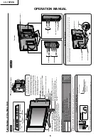


LC-15PX1U
14
ADJUSTING PROCEDURE OF EACH SECTION
The best adjustment is made before shipping. If any position deviation is found or after part replace is performed,
adjust as follows.
Preparation for Adjustments
Use the exclusive-use AC adapter or stable DC power supply.
AC adapter: UADP-A044WJPZ
DC power supply: 12 ± 0.5V 5.0A
1. Adjustment Procedure
1-1. Adjusting the checker
Turning on the power (initialization)
→
Setting the model and size in inches
→
Transferring the model-specified
data to the E
2
PROM (I
2
C)
→
Calling the adjustment process mode
→
Starting the adjustment
1-2. Adjusting the finish process
Reassembling the set
→
Turning on the power
→
Calling the adjustment process mode (using the remote
controller)
→
Adjusting the counter bias, TV contrast and white balance
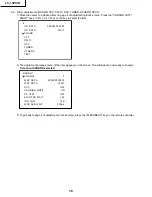
2. Calling the MAIN adjustment process mode
There are the following two ways to choose from.
• Set the Pin (81) (KEY4) or Pin (82) (KEY5) of IC2001 (microprocessor) to "L", turn on the power.
• For servicing, hold down the "TV/VIDEO" and "MENU" keys at once, and turn on the "POWER" switch. (Make
sure the process mode "K" appears at the top left of the screen.) Then press the "CH (
Ù
)" and "VOL (–)" keys
at once. (Make sure the adjustment process mode screen shows up.) To quit this mode, turn off the power. (Or
turn off the "POWER" switch or use the remote controller’s "OFF" key.)
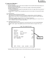
3. Using the keys for the adjustment process
Selecting a reception channel
• Using the "CH (
ù
)/(
Ù
)" key, turn up and down reception (broadcasting) channels.
Just click on the key, and channels are selected on by one.
Hold down the key, and the next receivable channel is searched up and down.
• Adjustment items
Adjust each of the items by using the "MENU", "CURSOR UP/DOWN" and "VOL (+)/(–)" keys (on the set or
on the remote controller).
• Select an adjustment item using the "CURSOR UP/DOWN" key.
• An adjustment item is toggled on and off by activating the MENU SELECT key (next item).
Let’s suppose that the item at the bottom of a page is now selected. When the "MENU" key is activated here,
the item at the top of the next page will be selected.
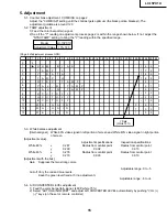
4. Initialization
4-1. Set pins (81) and (82) of IC2001 (microprocessor) to GND. Turn on the power.
4-2. Check model number (A621). (Can’t Change.)
4-3. Check the inch size (15). (Can’t Change.)
Содержание LC-15PX1U
Страница 27: ...LC 15PX1U 27 17 16 19 18 15 14 13 12 11 10 INVERTER Unit OPERATION Unit ANALOG Unit ...
Страница 30: ...LC 15PX1U 8 7 10 9 6 5 4 3 2 1 A B C D E F G H 30 OVERALL WIRING DIAGRAM ...
Страница 31: ...LC 15PX1U 31 17 16 19 18 15 14 13 12 11 10 ...
Страница 33: ...33 6 5 4 3 2 1 A B C D E F G H LC 15PX1U SCHEMATIC DIAGRAM Ë OPERATION Unit ...
Страница 34: ...LC 15PX1U 8 7 10 9 6 5 4 3 2 1 A B C D E F G H 34 ËMAIN Unit 1 14 ...
Страница 35: ...LC 15PX1U 35 17 16 19 18 15 14 13 12 11 10 ...
Страница 36: ...LC 15PX1U 8 7 10 9 6 5 4 3 2 1 A B C D E F G H 36 ËMAIN Unit 2 14 ...
Страница 37: ...LC 15PX1U 37 17 16 19 18 15 14 13 12 11 10 ...
Страница 38: ...LC 15PX1U 8 7 10 9 6 5 4 3 2 1 A B C D E F G H 38 ËMAIN Unit 3 14 ...
Страница 39: ...LC 15PX1U 39 17 16 19 18 15 14 13 12 11 10 ...
Страница 40: ...LC 15PX1U 8 7 10 9 6 5 4 3 2 1 A B C D E F G H 40 ËMAIN Unit 4 14 ...
Страница 41: ...LC 15PX1U 41 17 16 19 18 15 14 13 12 11 10 ...
Страница 42: ...LC 15PX1U 8 7 10 9 6 5 4 3 2 1 A B C D E F G H 42 ËMAIN Unit 5 14 ...
Страница 43: ...LC 15PX1U 43 17 16 19 18 15 14 13 12 11 10 ...
Страница 44: ...LC 15PX1U 8 7 10 9 6 5 4 3 2 1 A B C D E F G H 44 ËMAIN Unit 6 14 ...
Страница 45: ...LC 15PX1U 45 17 16 19 18 15 14 13 12 11 10 ...
Страница 46: ...LC 15PX1U 8 7 10 9 6 5 4 3 2 1 A B C D E F G H 46 ËMAIN Unit 7 14 ...
Страница 47: ...LC 15PX1U 47 17 16 19 18 15 14 13 12 11 10 ...
Страница 48: ...LC 15PX1U 8 7 10 9 6 5 4 3 2 1 A B C D E F G H 48 ËMAIN Unit 8 14 ...
Страница 49: ...LC 15PX1U 49 17 16 19 18 15 14 13 12 11 10 ...
Страница 50: ...LC 15PX1U 8 7 10 9 6 5 4 3 2 1 A B C D E F G H 50 ËMAIN Unit 9 14 ...
Страница 51: ...LC 15PX1U 51 17 16 19 18 15 14 13 12 11 10 ...
Страница 52: ...LC 15PX1U 8 7 10 9 6 5 4 3 2 1 A B C D E F G H 52 ËMAIN Unit 10 14 ...
Страница 53: ...LC 15PX1U 53 17 16 19 18 15 14 13 12 11 10 ...
Страница 54: ...LC 15PX1U 8 7 10 9 6 5 4 3 2 1 A B C D E F G H 54 ËMAIN Unit 11 14 ...
Страница 55: ...LC 15PX1U 55 17 16 19 18 15 14 13 12 11 10 ...
Страница 56: ...LC 15PX1U 8 7 10 9 6 5 4 3 2 1 A B C D E F G H 56 ËMAIN Unit 12 14 ...
Страница 57: ...LC 15PX1U 57 17 16 19 18 15 14 13 12 11 10 ...
Страница 58: ...LC 15PX1U 8 7 10 9 6 5 4 3 2 1 A B C D E F G H 58 ËMAIN Unit 13 14 ...
Страница 59: ...LC 15PX1U 59 17 16 19 18 15 14 13 12 11 10 ...
Страница 60: ...LC 15PX1U 8 7 10 9 6 5 4 3 2 1 A B C D E F G H 60 ËMAIN Unit 14 14 ...
Страница 61: ...LC 15PX1U 61 17 16 19 18 15 14 13 12 11 10 ...
Страница 62: ...LC 15PX1U 8 7 10 9 6 5 4 3 2 1 A B C D E F G H 62 ËANALOG Unit 1 4 ...
Страница 63: ...LC 15PX1U 63 17 16 19 18 15 14 13 12 11 10 ...
Страница 64: ...LC 15PX1U 8 7 10 9 6 5 4 3 2 1 A B C D E F G H 64 ËANALOG Unit 2 4 ...
Страница 65: ...LC 15PX1U 65 17 16 19 18 15 14 13 12 11 10 ...
Страница 66: ...LC 15PX1U 8 7 10 9 6 5 4 3 2 1 A B C D E F G H 66 ËANALOG Unit 3 4 ...
Страница 67: ...LC 15PX1U 67 17 16 19 18 15 14 13 12 11 10 ...
Страница 68: ...LC 15PX1U 8 7 10 9 6 5 4 3 2 1 A B C D E F G H 68 ËANALOG Unit 4 4 ...
Страница 69: ...LC 15PX1U 69 17 16 19 18 15 14 13 12 11 10 ...
Страница 70: ...70 6 5 4 3 2 1 A B C D E F G H LC 15PX1U ËR C LED Unit ...
Страница 71: ...71 6 5 4 3 2 1 A B C D E F G H LC 15PX1U ËCARD LED Unit ...
Страница 72: ...72 6 5 4 3 2 1 A B C D E F G H LC 15PX1U ËCARD DETECT Unit ...
Страница 73: ...73 6 5 4 3 2 1 A B C D E F G H LC 15PX1U ËINVERTER Unit ...
Страница 78: ...LC 15PX1U 8 7 10 9 6 5 4 3 2 1 A B C D E F G H 78 ANALOG Unit Side A ...
Страница 79: ...LC 15PX1U 79 17 16 19 18 15 14 13 12 11 10 ...
Страница 82: ...82 6 5 4 3 2 1 A B C D E F G H LC 15PX1U INVERTER Unit Side A ...
Страница 103: ...103 LC 15PX1U PACKING OF THE SET R L L R S9 S1 S2 S8 S4 X5 X6 S6 X7 S5 S5 S3 X1 X2 X3 X4 X8 S7 ...


