LC-15A2E
6
DISASSEMBLY OF THE SET
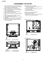
1. Insert your finger into the center of the terminal cover
and pull it toward you to detach the terminal cover.
Remove the screws installing a stand.
2. Remove the four screws
1
and one screw
2
.
3. Open the cabinet B by approx. 45˚ from the bottom
of the cabinet (stand side).
4. Remove the lead wire from the cable clamp
3
.
5. Remove the power connector
4
.
6. Remove the connector
5
from the light reception
unit.
7. Remove the lead wire from the cable clamp
6
.
8. Remove the speaker connector
7
.
9. Remove the FFC from the FFC connector
8
on the
main PWB.
10. Remove the connector
9
from the switch PWB.
11. Remove the right and left speaker connectors
0
on the terminal PWB.
<<Disassembly of the main PWB>>
1. Disconnect the flexible cable connectors
q
and
w
from the LCD panel.
2. Disconnect the cable connectors
e
and
r
from
the fluorescent lamp.
3. Remove the four screws
t
.
<<Disassembly of the terminal PWB>>
1. Remove the five screws
y
.
2. Remove the two screws
i
. Remove the cover
u
.
Take them out of the cabinet holes.
<<Cabinet A side>>
<<Cabinet B side>>
Cabinet A CCABA2402CE03
Terminal Cover GCOVA1922CEKA
Hinge Cover GCOVA1853CESA
Rotation Cover GCOVA1854CESA
Cabinet B CCABB2298CE01
Содержание LC-15A2E
Страница 15: ...LC 15A2E 15 M E M O ...
Страница 16: ...16 LC 15A2E A B C D E F G H I J 1 2 3 4 5 6 7 8 9 10 CHASSIS LAYOUT MAIN Unit Side A MAIN Unit Side B ...
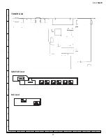
Страница 17: ...17 LC 15A2E A B C D E F G H I J 1 2 3 4 5 6 7 8 9 10 TUNER Unit SWITCH Unit R C Unit ...
Страница 20: ...22 LC 15A2E WAVEFORMS A V0 B V16 C V32 D V48 E V63 F B 5 5 G CSCOM H GCK I GSP J VACT K HC L HSY ...
Страница 21: ...23 LC 15A2E M VSY N CK O SPIO P SPOI Q HG R IC2005 S CSYNC T VIDEO ...
Страница 22: ...25 LC 15A2E Ë SWITCH and R C Unit A B C D E F G H I J 1 2 3 4 5 6 7 8 9 10 SCHEMATIC DIAGRAMS ...
Страница 26: ...32 LC 15A2E A B C D E F G H I J 1 2 3 4 5 6 7 8 9 10 PRINTED WIRING BOARD ASSEMBLIES Main Unit Side A ...
Страница 27: ...33 LC 15A2E Main Unit Side B A B C D E F G H I J 1 2 3 4 5 6 7 8 9 10 ...
Страница 28: ...34 LC 15A2E A B C D E F G H I J 1 2 3 4 5 6 7 8 9 10 Tuner Unit Side A ...
Страница 29: ...35 LC 15A2E A B C D E F G H I J 1 2 3 4 5 6 7 8 9 10 Tuner Unit Side B ...


