


REMOVE OF THERMISTOR PLATE ASS’Y
1. Remove the body in accordance with “REMOVE OF BODY”.
2. Disconnect all lead wire of the thermistor plate ass’y from PCB ASS’Y.
3. Unbend the lead wire band bounding all the lead wire.
4. Remove the heater plate ass’y in accordance with “REMOVE OF HEATER PLATE ASS’Y”.
5. Twist 2 claws of thermistor plate ass’y.
6. Now the thermistor plate ass’y is free.
15
DISENGAGE PCB ASS’Y
1. Remove body in accordance with “REMOVE BODY”.
2. Disconnect all the lead wires of PCB ass’y.
3. Remove the 3 screws fixing the PCB ass’y to the panel ring. (Fig. 6.)
4. Now the PCB ass’y is free.
Fig. 6.
Always replace the display cushion because it may be damaged.
CAUTION
Fig. 7.
1. Remove body in accordance with “REMOVE OF BODY”.
2. Remove thermistor plate ass’y in accordance with “REMOVE OF THERMISTOR PLATE ASS’Y.
3. Turning the outer pot counterclockwise.
4. Now the outer pot is free.
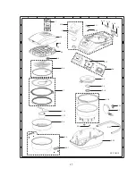
REMOVE OF OUTER POT
Outer pot
Screw
PCB ass’y
Upper ring
Содержание KS-COM18
Страница 8: ...8 WIRING DIAGRAM CIRCUIT DIAGRAM ...
Страница 10: ...10 ...


