UX-44U
FO-55C
CHAPTER 3. MECHANISM BLOCKS
[1] General description
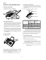
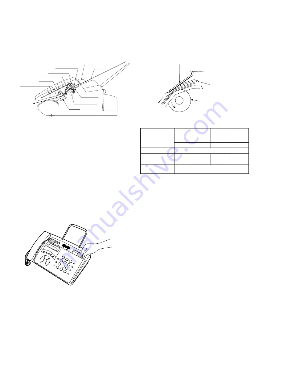
1. Document feed block and diagram
Fig. 1
2. Document feed operation
1) The original, which is set in the document hopper, feeds automati-
cally when the front sensor is activated. This in turn activates the
pulse motor which drives the document supply roller. The document
stops when the lead edge is detected by the document sensor.
2) The lead edge of the original is fed a specified number of pulses after
the lead edge of the document is detected for the reading process to
begin.
3) The trailing edge of the original is fed a specific number of pulses
after the trailing edge of the document deactivates the document
sensor. The read process then stops and the original is discharged.
4) When the front sensor is in the OFF state (any document is not set
up in the hopper guide), the drive will be stopped when the docu-
ment is discharged.
3. Hopper mechanism
3-1. General view
3-2. Automatic document feed
1) Use of the paper feed roller and separation rubber plate ensures er-
ror-free transport and separation of documents. The plate spring
presses the document to the paper feed roller to assure smooth feed-
ing of the document.
2) Document separation method: Separation rubber plate
Fig. 3
3-3. Documents applicable for automatic feed
NOTE: Double-side coated documents and documents on facsimile re-
cording paper should be inserted manually. The document feed
quantity may be changed according to the document thickness.
Documents corresponding to a paper weight heavier than 69.2kg (80g/
m
2
) and lighter than 135kg (157g/m
2
) are acceptable for manual feed.
Documents heavier than 135kg in terms of the paper weight must be
duplicated on a copier to make it operative in the facsimile.
3-4. Loading the documents
1) Make sure that the documents are of suitable size and thickness, and
free from creases, folds, curls, wet glue, wet ink, clips, staples and
pins.
2) Place documents face down in the hopper.
i) Adjust the document guides to the document size.
ii) Align the top edge of documents and gently place them into the
hopper. The first page under the stack will be taken up by the feed
roller to get ready for transmission.
NOTES:
1) Curled edge of documents, if any, must be straightened
out.
2) Do not load the documents of different sizes and/or
thicknesses together.
3 – 1
Paper size
148mm x 140mm ~
A4 (210mm x 297mm), Letter (216mm x 279mm)
4x6 series
(788mm x 1091mm x
1000mm sheets)
Square
meter series
Minimum
Maximum
Minimum
Maximum
Feeder capacity
5 sheets, max.
Paper thickness (ref.)
0.06mm
0.09mm
0.06mm
0.09mm
Paper weight
45kg
69.2kg
52g/m
2
80g/m
2
,,,,,,,,,,,,
,,,,,,,,,,,,
,,,,,,,,,,,,
,,,,,,,,,,,,
,,,,,,,,,,,,
,,,,,,,,,,,,
,,,,,,,,,,,,
,,,,,,,,,,,,
,,,,,,,,,,,,
Separation rubber
Feed plate
Document
Paper feed roller
Operation panel PWB
Back roller
Document sensor
Separator plate
Separator rubber
Hopper guide
Document
Front sensor
Paper feed roller
CIS unit
Fig. 2
The hopper section contains document guides that are used to adjust
the hopper to the width of the original document. This ensures that the
original feeds straight into the fax machine for scanning.
Document width: 148 mm to 216 mm (A5 longitudinal size to Letter
longitudinal size)
NOTE: Adjust the document guide after setting up the document.
Содержание FO-55
Страница 48: ...UX 44U FO 55C M E M O 5 13 ...
Страница 55: ...UX 44U FO 55C Control PWB parts layout Top side 6 7 ...
Страница 56: ...UX 44U FO 55C Control PWB parts layout Bottom side 6 8 ...
Страница 59: ...UX 44U FO 55C TEL LIU PWB parts layout Top side 6 11 ...
Страница 60: ...UX 44U FO 55C 6 12 TEL LIU PWB parts layout Bottom side ...
Страница 66: ...UX 44U FO 55C 6 18 M E M O ...

