background image

32

R-1512

R-1511

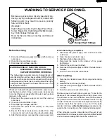
PRECAUTIONS TO BE OBSERVED BEFORE AND
DURING SERVICING TO AVOID POSSIBLE EXPO-
SURE TO EXCESSIVE MICROWAVE ENERGY

(a) Do not operate or allow the oven to be operated with the door open.
(b) Make the following safety checks on all ovens to be serviced before activating the magnetron or other

microwave source, and make repairs as necessary: (1) interlock operation, (2) proper door closing, (3) seal
and sealing surfaces (arcing, wear, and other damage), (4) damage to or loosening of hinges and latches,
(5) evidence of dropping or abuse.

(c) Before turning on microwave power for any service test or inspection within the microwave generating

compartments, check the magnetron, wave guide or transmission line, and cavity for proper alignment,
integrity, and connections.

(d) Any defective or misadjusted components in the interlock, monitor, door seal, and microwave generation

and transmission systems shall be repaired, replaced, or adjusted by procedures described in this manual
before the oven is released to the owner.

(e) A microwave leakage check to verify compliance with the Federal Performance Standard should be

performed on each oven prior to release to the owner.

BEFORE SERVICING

Before servicing an operative unit, perform a microwave emission check as per the Microwave
Measurement Procedure outlined in this service manual.
If microwave emissions level is in excess of the specified limit, contact SHARP ELECTRONICS
CORPORATION immediately  @1-800-237-4277.

If the unit operates with the door open, service person should 1) tell the user not to operate the oven
and 2) contact SHARP ELECTRONICS CORPORATION and Food and Drug Administration's
Center for Devices and Radiological Health immediately.

Service personnel should inform SHARP ELECTRONICS CORPORATION of any certified unit
found with emissions in excess of 4mW/cm

2

. The owner of the unit should be instructed not to use

the unit until the oven has been brought into compliance.

Содержание Carousel R-1512

Страница 1: ...RSONNEL 1 MICROWAVE MEASUREMENT PROCEDURE 2 FOREWORD AND WARNING 3 PRODUCT SPECIFICATIONS 4 CONTROL PANEL 5 OPERATION 5 TROUBLESHOOTING GUIDE 7 TEST PROCEDURE 8 TOUCH CONTROL PANEL ASSEMBLY 14 COMPONENT REPLACEMENT AND ADJUSTMENT PROCEDURE 19 PICTORIAL DIAGRAM 22 POWER UNIT CIRCUIT 23 LSI UNIT CIRCUIT 24 PRINTED WIRING BOARD 25 PARTS LIST 26 PACKING AND ACCESSORIES 28 S73M213R1512E R 1512 OVER THE...

Страница 2: ... and transmission systems shall be repaired replaced or adjusted by procedures described in this manual before the oven is released to the owner e A microwave leakage check to verify compliance with the Federal Performance Standard should be performed on each oven prior to release to the owner BEFORE SERVICING Before servicing an operative unit perform a microwave emission check as per the Microwa...

Страница 3: ...citor 4 Disconnect the leads to the primary of the power transformer 5 Ensure that these leads remain isolated from other components and oven chassis by using insulation tape 6 After that procedure reconnect the power supply cord When the testing is completed 1 Disconnect the power supply cord and then remove outer case 2 Open the door and block it open 3 Discharge high voltage capacitor 4 Reconne...

Страница 4: ...y The water container shall be a low form of 600 ml 20 oz beaker with an inside diameter of approx 8 5 cm 3 1 2 in and made of an electrically nonconductive material such as glass or plastic The placing of this standard load in the oven is important not only to protect the oven but also to insure that any leakage is measured accurately 4 Set the cooking control on Full Power Cooking Mode 5 Close t...

Страница 5: ...r operate the oven until the following points are ensured A The door is tightly closed B The door brackets and hinges are not defective C The door packing is not damaged D The door is not deformed or warped E There is not any other visible damage with the oven Servicing and repair work must be carried out only by trained service personnel DANGER Certain initial parts are intentionally not grounded...

Страница 6: ...ghout the cooking time P 90 approx 90 of Full Power P 80 approx 80 of Full Power P 70 approx 70 of Full Power P 60 approx 60 of Full Power P 50 approx 50 of Full Power P 40 approx 40 of Full Power P 30 approx 30 of Full Power P 20 approx 20 of Full Power P 10 approx 10 of Full Power P 0 No power throughout the cooking time KEEP WARM PLUS pad HOT WATER pad CUSTOM HELP pad INSTANT SENSOR pads SENSOR...

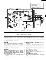
Страница 7: ... condition the monitor switch contacts are opened When oven is plugged in 120 volts A C is supplied to the control unit Figure O 1 1 The display will show SHARP SIMPLY THE BEST PRESS CLEAR AND PRESS CLOCK To set any program or set the clock you must first touch the STOP CLEAR button The display will clear and will appear POWER LEVEL P 0 TO P 90 COOKING When Variable Cooking Power is programmed the...

Страница 8: ...ergized the oven lamp turntable motor and cooling fan motor are turned on but the power transformer is not turned on 3 Afterabout32seconds thecookrelay RY2 isenergized The power transformer is turned on microwave energy is produced and first stage is started The 32 seconds is the cooling time required to remove any vapor from the oven cavity and sensor NOTE During this first stage do not open the ...

Страница 9: ...found in the Test Procedure section IMPORTANT If the oven becomes inoperative because of a blown moni tor fuse check the monitor switch relay RY1 secondary interlock relay RY2 door sensing switch and primary interlockswitchbeforereplacingthemonitorfuse If monitor fuse is replaced the monitor switch must also be replaced Use part FFS BA016 KiT as an assembly IMPORTANT Whenever troubleshooting is pe...

Страница 10: ... the symptoms indicated Before testing 1 Disconnect the power supply cord and then remove outer case Refer to procedure of HOOD EXHAUST LOUVER REMOVAL REMOVAL OF OVEN FROM WALL and OUTER CASE REMOVAL 2 Open the door and block it open 3 To discharge high voltage capacitor wait for 60 seconds 4 Remove two 2 screws holding the hood intake duct R to the ovencavity top plate and the base plate R And re...

Страница 11: ...nnect all leads removed from components during testing 5 Re install the hood intake duct R 6 Re install the outer case cabinet 7 Reconnect the power supply cord after the outer case is installed 8 Run the oven and check all functions 1 Disconnect the power supply cord 2 Open the door and block it open 3 To discharge high voltage capacitor wait for 60 seconds 4 Remove the control panel assembly 5 I...

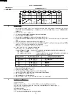
Страница 12: ... connected to the relay coil If diode is good control unit is defective RELAY SYMBOL OPERATIONAL VOLTAGE CONNECTED COMPONENTS RY1 Approx 25 0V D C Oven lamp Fan motor Turntable motor RY2 COOK Approx 24 5V D C Power transformer RY3 Approx 25 0V D C Hood motor RY4 Approx 25 0V D C Hood motor RY5 Approx 25 0V D C Hood lamp RY6 Approx 25 0V D C Hood lamp 9 Disconnect the power supply cord 10 Open the ...

Страница 13: ...place the defective parts 7 Reconnect all leads removed from components during testing 8 Re install the control unit to the control panel and re install the control panel to the oven 9 Reconnect the power supply cord 10 Run the oven and check all functions 2 Follow the troubleshooting guide given below if indicator does not light up after above check and repairs are finished 1 Disconnect the power...

Страница 14: ...he sensor will detect the vapor given of by the spray and turn off before food is properly cooked 8 If the sensor has not detected the vapor of the food ERROR will appear and the oven will shut off Water load cooking test WARNING The oven should be fully assembled before following procedure Make sure the oven has been plugged in at least two minutes before checking sensor cook operation The cabine...

Страница 15: ...er components and oven chassis by using insulation tape 8 After that procedure re connect the power supply cord 9 Check the sensor cook operation proceed as follows 9 1 Touch the TIMER CLOCK pad once the POWER LEVEL pad twice the START pad once and the number pad 1 once and the number pad 4 once 9 2 The control panel is in the sensor cooking operation 9 3 After approximately 65 seconds push plunge...

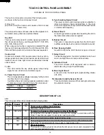
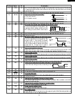
Страница 16: ... the LSI are sent to the key unit through P20 P21 P22 P23 P24 P25 P26 and P27 When a key pad is touched a signal is completed through the key unit and passed back to the LSI through P43 P44 P45 and P46 to perform the function that was requested Control Unit Control unit consists of LSI power source circuit synchro nizing signal circuit reset circuit buzzer circuit relay circuit indicator circuit b...

Страница 17: ... the signal is held at H level 21 P45 IN Signal similar to P46 WheneitherG11lineonkeymatrixistouched acorrespondingsignalwillbeinputintoP45 22 P44 IN Signal similar to P46 WheneitherG10lineonkeymatrixistouched acorrespondingsignalwillbeinputintoP44 23 P43 IN Signal similar to P46 When either G9 line on key matrix is touched a corresponding signal will be input into P43 24 INT0 IN Signal synchroniz...

Страница 18: ...Y6 L level During Hood lamp ON H level During Hood lamp OFF 42 P16 OUT Hood lamp driving signal To turn on and off relay RY5 L level During Hood lamp ON H level During Hood lamp OFF 43 P15 OUT Hood motor high low driving signal To turn on and off relay RY3 L level During Hood motor high H level During Hood motor low 44 P14 OUT Hood motor driving signal To turn on and off relay RY4 L level During H...

Страница 19: ...ction and the LSI observes the initial voltage available at its AN1 terminal With this voltage given the switches SW1 to SW5 in the LSI are turned on in such a way as to change the resistance values in parallel with R98 R102 of IC2 Changing the resistance values results in that there is the same potential at both F 3 terminal of the absolute humiditysensorandAN0terminaloftheLSI Thevoltage of AN1 t...

Страница 20: ...f is so short that the two can t be separated For those models check and repair all the controls sensor related ones included of the touch control panel while keeping it connected to the oven B On some models the power supply cord between the touch control panel and the oven proper is long enough that they may be separated from each other For those models it is possible to check and repair the con...

Страница 21: ...of the following conditions exist 1 Door does not close firmly 2 Door hinge support or latch hook is damaged 3 The door gasket or seal is damaged 4 The door is bent or warped 5 There are defective parts in the door interlock system 6 There are defective parts in the microwave generating and transmission assembly 7 There is visible damage to the oven Do not operate the oven 1 Without the RF gasket ...

Страница 22: ...2 Disconnect the connector CN G from the control unit 13 Remove the two 2 screws holding the LCD holder to the key fixing plate 14 Remove two 2 screws holding the power unit to the key fixing plate 15 Releasethetwo 2 tabsholdingthepowerunittothekey fixing plate 16 Release the three 3 tabs holding the LCD to the LCD holder 17 Release the two 2 tabs holding the LSI unit to the LCD holder 18 Remove t...

Страница 23: ...o procedure of HOOD EXHAUST LOUVER REMOVAL 5 Remove one 1 screw holding the control panel to the oven cavity front face plate 6 Release the control panel from the oven cavity front face plate by lifting it up and tilting top edge back 7 Turn the lamp socket and release it from the magnetron duct OVEN LAMP SOCKET REMOVAL Oven lamp socket Terminal Wire lead Terminal hole Flat type small screw driver...

Страница 24: ...T HOOD LAMP SOCKET CN E GRY WHT WHT WHT WHT RED PRIMARY INTERLOCK SWITCH N O N C COM COM MONITOR SWITCH FUSE HOLDER N O N O GRN RED GRN GRN GRN N O COM DOOR SENSING SWITCH CN B CN C CN G CN C CN A CN E 1 9 1 1 2 1 14 5 SECONDARY INTERLOCK RELAY RY1 RY3 RY2 RY4 C100 T1 HOOD FAN MOTOR 1 2 3 4 5 6 WHT RED YLW BLU BLK WHT RED YLW BLU BLK 1 2 RED GRN 1 2 3 4 5 YLW RED PPL CN A TURNTABLE MOTOR WHT BRN H...

Страница 25: ...0v C2 1000 35v C3 10 35v ZD1 HZ16 1 1 5 D3 D1 D2 SP1 PKM22EPT Q21 KRC243M C21 10 35v D1 D4 1N4002 C100 7 230v R2 510 1 2w Q1 2SB1238 R1 330 1w AC N OVEN LAMP TURNTABLE MOTOR FAN MOTOR OVEN LAMP TURNTABLE MOTOR FAN MOTOR CN C 14pin WIRE HARNESS BUZZER MICRO GND VC VA INT HOOD THERMAL CUT OUT AC H MICRO HIGH LOW CN B CN A CN E HOOD MOTOR HOOD MOTOR COM HOOD MOTOR H L HOOD MOTOR COM HOOD LAMP HOOD LA...

Страница 26: ...8 SEG9 SEG10 SEG11 SEG12 SEG13 SEG14 SEG15 SEG16 SEG17 SEG18 SEG19 SEG20 SEG21 SEG22 SEG23 SEG24 COM1 COM2 COM3 COM1 LCD COM2 LCD COM3 LCD COM4 LCD COM0 LCD COM1 LCD COM2 LCD COM3 LCD AVSS VREF VCC SEG0 SEG1 SEG2 SEG3 SEG4 SEG5 SEG6 SEG7 VL1 AN7 AN6 AN5 AN4 AN3 AN2 AN1 AN0 P57 P56 P55 CNTR0 P53 P52 P51 P50 P47 P46 P45 P44 P43 INT0 SEG14 SEG9 SEG15 SEG10 SEG11 SEG12 SEG13 SEG14 SEG15 SEG16 SEG16 SE...

Страница 27: ... S 4 Printed Wiring Board 0 F C S M 2 7 A 9 4 V 0 M B M R 3 5 0 R BFB DIP LOT NO QKITPB035MRE0 RY1 VRS1 R30 T1 S 8 5 1 3 P C100 D26 D24 D23 D22 C21 CN E CN C D21 D40 D20 2 1 R2 Q21 Q1 B B ZD1 E E R1 R3 C2 D1 D3 D4 D2 D25 1 1 9 5 RY5 CN B CN A C1 C3 1 1 2 14 SP1 J1 RY2 RY3 RY4 RY6 ...

Страница 28: ...c diagram 1 AB 2 7 FANGKB013MRY0 M Hood lamp glass assembly 1 AK 2 7 1 LANGQB049MRP0 M Hood lamp glass angle 1 AG 2 7 2 PGLSPB004MRE0 M Hood lamp glass 1 AH 2 8 PCOVPB102MRT0 M Base cover 1 AQ CONTROL PANEL PARTS 3 1 CPWBFB076MRU0 M Control unit 1 BE 3 1A QCNCMA017JDZZ M 3 pin connector CN A 1 AG 3 1B QCNCMA448DRE0 M 5 pin connector CN B 1 AF 3 1C QCNCMA275DRE0 J 2 pin connector CN E 1 AB 3 1D FW ...

Страница 29: ...ion 1 AC 4 23 PCUSUB045MRP0 M Cushion 1 AC 4 24 PCUSUB019MRP0 M Cushion 1 AC 4 25 PCUSUB061MRP0 M Cushion 1 AC DOOR PARTS 5 CDORFB342MRK0 M Door assembly 1 BF 5 1 FDORFB070MRT0 M Door panel assembly 1 AW 5 2 FCOV B248MRK0 M Door frame assembly 1 AZ 5 2 1 LSTPPB023MRF0 M Latch head 1 AC 5 2 2 MSPRTA046WRE0 M Latch spring 1 AB 5 2 3 LSTPPB037MRF0 M Glass stopper 2 AC 5 3 GCOVHB044MRF0 M Choke cover ...

Страница 30: ...Scale plate 2 AD SCREWS NUTS AND WASHERS 7 1 LX CZB016MRE0 M Special screw 3 AA 7 2 XOTSD40P12000 M Screw 4mm x 12mm 5 AA 7 3 XOTSE40P12000 M Screw 4mm x 12mm 29 AA 7 4 XHTSD40P08RV0 M Screw 4mm x 8mm 2 AA 7 5 LX CZ0052WRE0 M Special screw 2 AA 7 6 LX WZB003MRE0 M Sensor washer 1 AA 7 7 XCBSD30P08000 M Screw 3mm x 8mm 5 AA 7 8 LX BZA041WRE0 M Special screw 5 AA PACKINGANDACCESSORIES 4 3 TURNTABLE ...

Страница 31: ... 7 3 7 3 7 3 7 3 6 8 7 3 6 13 7 3 4 13 2 4 4 7 4 15 4 8 6 11 2 8 1 13 7 2 1 16 7 2 7 2 1 4 1 11 2 7 6 11 1 10 4 21 7 7 1 11 1 9 4 13 4 14 4 16 4 16 4 20 4 5 1 7 4 22 1 6 7 3 7 3 7 3 7 3 2 3 4 9 7 4 1 8 1 16 1 13 4 6 4 3 4 2 4 11 7 7 7 3 7 2 7 3 2 5 1 17 7 6 6 14 6 16 7 7 7 7 4 19 6 12 2 1 7 3 7 3 7 3 4 12 1 12 7 3 1 3 1 15 1 2 1 1 4 4 7 8 2 7 1 2 7 2 1 5 7 7 7 8 4 25 ...

Страница 32: ...6 4 5 1 2 3 A B C D E F G H A B C D E F G H 6 4 6 5 6 9 6 1 6 1 1 6 1 2 6 1 3 6 1 7 6 15 6 1 5 6 1 6 6 1 4 5 2 3 3 2 3 3 2 1 3 2 2 5 2 3 5 2 2 5 2 1 5 2 5 3 5 4 5 1 5 4 1 5 5 5 5 3 3 3 2 4 3 2 7 3 3 5 3 5 3 1 3 4 3 5 CONTROL PANEL PARTS MISCELLANEOUS DOOR PARTS ...

Отзывы: