


AR-MS1 UNPACKING AND INSTALLATION 4-1
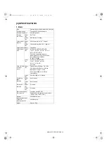
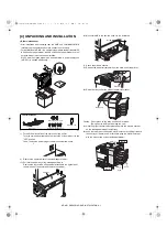
[4] UNPACKING AND INSTALLATION
<Before installation>
•Start installation after checking that the DATA and COMMUNICATION
indicators on the operation panel are neither lit nor blinking.
•For installation of AR-MS1, an optional stand/paper drawer (stand/MPD
& 2000 sheet paper drawer, stand/3 x 500 sheet paper drawer or multi
purpose drawer) must have been installed.
Also if a multi purpose drawer has been installed, a power supply unit
(AR-DC1) is needed additionally.
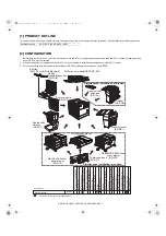
1) Turn off the main switch of the main unit of the printer.
Turn the main switch located on the front side of the main unit to the
"OFF" position.
Then, remove the power plug of the main unit from the outlet.
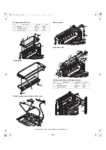
2) Remove the upper cabinet of the stand/paper drawer.
<1>Pull out the paper tray of the stand/paper drawer.
Remove the four screws of the cabinet attached to the right side of
the main unit of the printer and remove the cabinet.
<2>Mount screw B to the position shown in the illustration.
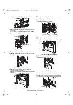
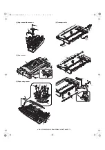
3) Attach the mail-bin stacker.
<1>Remove the paper exit actuator from the main unit of the printer.
<2>Raise the relay unit at the side of the mail-bin stacker.
Caution: Do not press on the relay unit while it is raised.
(Doing so may deform or damage the unit.)
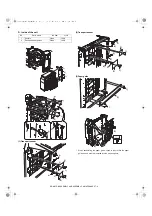
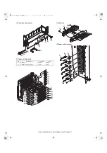
<3>Hold the grip of the mail-bin stacker and place the mail-bin stacker
on the stand/paper drawer temporarily.
<4>push the lower part to attach the mail-bin stacker by sliding it toward
the exit tray of the main unit. At this time, align the mail-bin stacker
with the exterior line of the stand/paper drawer.
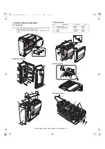
<Parts included>
Mounting plates: 2 pcs.
Tray: 1 pc.
Screw B: 1 pc.
Screws A (M4x8): 5 pcs.
"OFF"
Cabinet
Screw B
Actuator
Relay unit
Push.
Push.
Place.
Grip
Grip
"# $%&'()