


AR-M150/M155/M155X DISASSEMBLY AND ASSEMBLY 8 - 12
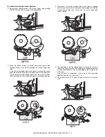
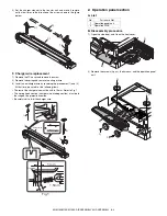
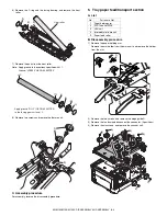
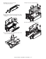
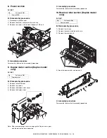
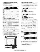
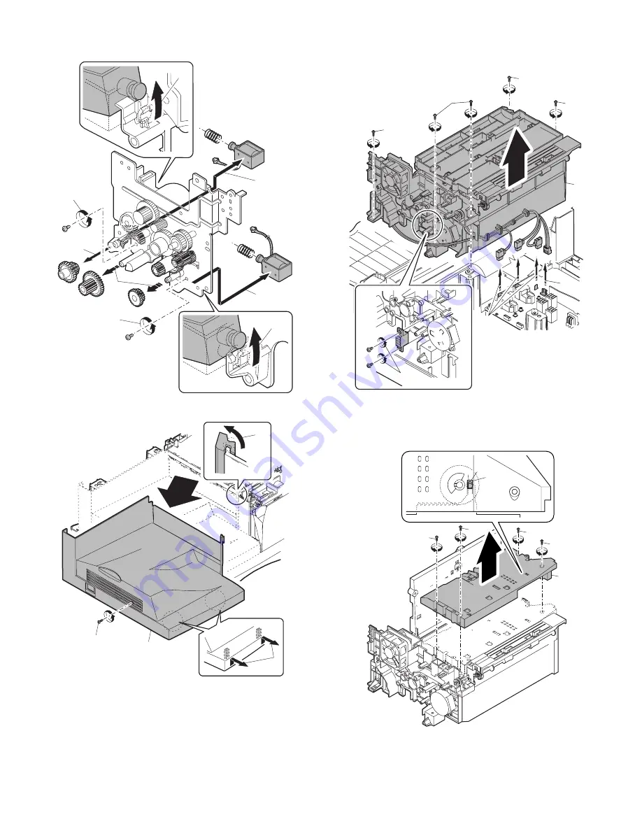
21) Remove the parts as shown below, and remove the pressure
release solenoid and the paper feed solenoid.
22) Remove each pawl, and remove the paper exit tray.
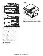
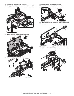
23) Remove two screws and remove the fusing connector.
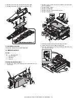
24) Remove five screws and the connector, and lift the intermediate
frame unit to remove.
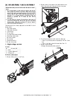
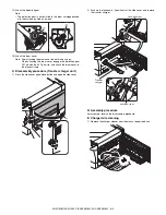
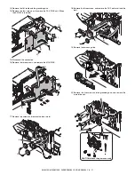
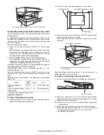
25) Remove the four screws, and remove the lower paper guide unit.
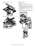
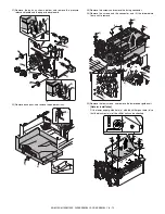
[Note for installation]
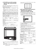
Fit the lower paper guide hole (a) with the shifter gear hole (b) so
that the black resin (c) of the shifter unit can be checked.
3)
3)
1)
1)
2)
2)
4)
4)
2)
4)
1)
3)
2)
2)
3)
3)
3)
3)
1)
4)
1)
1)
1)
1)
2)
a
b
c
Содержание AR-M150 Online
Страница 152: ...AR M150 M155 M155X CIRCUIT DIAGRAM 14 29 3 POWER SUPPLY A 1 2 3 4 5 6 B C D E F G H 1 2 3 4 5 6 POWER SUPPLY 120V 127V ...
Страница 153: ...AR M150 M155 M155X CIRCUIT DIAGRAM 14 30 6 7 8 9 10 11 12 6 7 8 9 10 11 12 A B C D E F G H 1 1 ...
Страница 154: ...AR M150 M155 M155X CIRCUIT DIAGRAM 14 31 A 1 2 3 4 5 6 B C D E F G H 1 2 3 4 5 6 POWER SUPPLY 220V 240V ...
Страница 155: ...AR M150 M155 M155X CIRCUIT DIAGRAM 14 32 6 7 8 9 10 11 12 6 7 8 9 10 11 12 A B C D E F G H 1 1 ...
Страница 167: ...Memo ...
Страница 168: ...Memo ...
Страница 169: ...Memo ...


