background image

LC-52/60LE830E,RU/830E,S/833E

 7

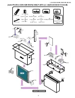
[5] SUPPLIED ACCESSORIES/PACKING PARTS (LC-52LE830E,RU/831E,S/833E)

S12

S1

S6

S3

S4

FRONT

S9

S10

S4

S4

S7

S8

X2

X17

X14

X1

X6

X7

X8

X9

S5

S5

S5

S2

Operation manual

Remote control

“AAA” size battery

Cable Clamp

X14

X2

X1

X17

X12

X4

X10

X20

Guarantee Card

X3

Wireless LAN USB

adapter

X13

USB memory

X5

SAFETY SHEET

X6

WEEE SHEET

X7

Wifi SHEET

X8

DONGLE SHEET

X9

Skype SHEET

X19

GOST SHEET

X21

GUARANTEE/AQUOS

S13

S13

X5

X10

X19

X20

X21

X4

X12

X13

S12

X18

GOST SHEET

S14

X3

Содержание Aquos LC-52LE830E

Страница 1: ...ing specification at the time of the error 6 18 CHAPTER 7 MAJOR IC INFORMATIONS 1 MAJOR IC INFORMATIONS 7 1 CHAPTER 8 OVERALL WIRING SYSTEM BLOCK DIAGRAM 1 OVERALL WIRING DIAGRAM LC 52LE830E RU 833E 8 1 2 OVERALL WIRING DIAGRAM LC 52LE831E S 8 2 3 OVERALL WIRING DIAGRAM LC 60LE830E RU 833E 8 3 4 OVERALL WIRING DIAGRAM LC 60LE831E S 8 4 5 SYSTEM BLOCK DIAGRAM LC 52 60LE830E RU 833E 8 5 6 SYSTEM BLO...

Страница 2: ...easure the AC voltage drop across the resistor All checks must be repeated with the AC cord plug connection reversed If necessary a nonpolarized adaptor plug must be used only for the purpose of completing these checks Any reading of 1 05 V peak this corresponds to 0 7 mA peak AC or more is excessive and indicates a potential shock hazard which must be corrected before returning the monitor to the...

Страница 3: ...entional lead solder by 40 C and as it has poor solder wettability you may be apt to keep the soldering bit in contact with the PWB for extended period of time However Since the land may be peeled off or the maximum heat resistance temperature of parts may be exceeded remove the bit from the PWB as soon as you confirm the steady soldering condition Lead free solder contains more tin and the end of...

Страница 4: ...LC 52 60LE830E RU 831E S 833E iii End of life disposal End of life disposal ...

Страница 5: ...2LE830E RU 831E S 833E N RUNTKA799WJN1 POWER SUPPLY Unit LC 60LE830E RU 831E S 833E N RUNTK4909TPYX LCD CONTROL Unit LC 52LE830E RU 831E S 833E N RUNTK4909TPYN LCD CONTROL Unit LC 60LE830E RU 831E S 833E Ref No Parts No Description N R1LK520D3GW4BY 52 LCD Panel Module Unit LK520D3GW4BY LC 52LE830E RU 831E S 833E N R1LK600D3GW4BH 60 LCD Panel Module Unit LK600D3GW4BH LC 60LE830E RU 831E S 833E Ref ...

Страница 6: ... EXT 3 Component AV input Audio L R PC mini D sub 15 pin HDMI 1 EXT 4 HDMI ARC HDMI 2 EXT 5 HDMI HDMI 3 EXT 6 HDMI HDMI 4 EXT 7 HDMI USB 1 USB USB 2 HDD USB USB 3 WIRELESS LAN USB ETHERNET 10 100 Network connector HDMI 2 PC AUDIO L R Ø 3 5 mm jack 2 DIGIT AL AUDIO OUTPUT Optical S PDIF digital audio output C I Common Interface EN50221 R206001 CI Plus specification OUTPUT Headphones RCA pin AUDIO L...

Страница 7: ...SB 1 USB USB 2 HDD USB USB 3 WIRELESS LAN USB ETHERNET 10 100 Network connector HDMI 2 PC AUDIO L R Ø 3 5 mm jack 2 DIGITAL AUDIO OUTPUT Optical S PDIF digital audio output C I Common Interface EN50221 R206001 CI Plus specification OUTPUT Headphones RCA pin AUDIO L R Ø 3 5 mm jack audio output SD CARD VIDEO STORE SD card OSD language Czech Danish Dutch English Estonian Finnish French German Greek ...

Страница 8: ...en viewing 3D images Do not place anything between the 3D infrared emitter on the TV and the infrared receiver on the 3D glasses TV rear view USB 3 WIRELESS LAN port USB 2 HDD port ETHERNET 10 100 terminal Satellite antenna terminal 830 833 series only Antenna terminal DIGITAL AUDIO OUTPUT terminal HDMI 2 PC AUDIO L R jack 3 3 The HDMI 2 and PC terminals can both use the same audio input terminal ...

Страница 9: ...POWER switch is turned off the amount of electric power consumed will be reduced to 0 01 W or less However unlike when unplugging the AC cord the power is not completely disconnected 5 When a cable is connected to the OUTPUT terminal the speakers do not output sound WARNING Excessive sound pressure from earphones and headphones can cause hearing loss Do not set the volume at a high level Hearing e...

Страница 10: ...ROL Display a panel to operate some functions on the screen NET NET MENU screen on off 5 TIME SHIFT READY Temporarily record a programme you are watching 6 Numeric buttons 0 9 Set the channel Enter desired numbers Set the page in teletext mode When the five Nordic countries Sweden Norway Finland Denmark or Iceland are selected in the country setting from initial auto installation DTV services are ...

Страница 11: ...ings ECO Standard Advanced Off Select Energy save setting 19 Teletext ATV Display analogue teletext DTV SAT Select MHEG 5 or teletext for DTV SAT 20 ATV DTV SAT Select the TV channel NET Scrolls pages up down 21 EPG DTV SAT Display the EPG screen 22 Return ATV DTV SAT Return to the previous Menu screen NET Return to the previous page This may not function for some services 23 Buttons for useful op...

Страница 12: ... base using the long screws with a screwdriver as shown Supporting post 60 inch models 52 inch models 3 Insert the stand into the openings on the bottom of the TV hold the stand so it will not drop from the edge of the base area Make sure that the stand is firmly inserted into the TV Improper installation may result in tilting of the TV set Soft cushion 60 inch models 52 inch models 4 Insert and t...

Страница 13: ... 0 180 0 19 0 400 0 180 0 19 0 215 0 400 0 215 0 1206 0 787 0 738 0 507 0 1152 0 1 1206 0 507 0 1152 0 1 33 4 33 4 3 26 4 26 4 2 648 0 1 787 0 738 0 648 0 1 436 0 436 0 142 0 142 0 298 0 298 0 1 Active area 2 Thinnest part 3 Excluding projecting part NOTE Dimensions do not include protrusions such as screws and some parts Unit mm ...

Страница 14: ...0 839 0 486 0 536 0 215 0 400 0 215 0 1329 12 1 536 0 1329 12 1 355 0 355 0 33 4 33 4 3 26 4 26 4 2 747 63 1 400 0 230 0 52 0 888 0 839 0 486 0 747 63 1 169 0 1383 0 169 0 1 Active area 2 Thinnest part 3 Excluding projecting part NOTE Dimensions do not include protrusions such as screws and some parts Unit mm ...

Страница 15: ...e the 1 lock screw and detach the Stand Support Cover 2 Remove the 4 lock screws and detach the Stand Unit 3 Remove the 1 lock screw and detach the AC Cord Cover 4 Disconnect AC Cord 5 Remove the 4 Vesa Hole Covers 7 lock screws and 13 lock screws and 3 lock screws and detach the Rear Cabinet Ass y 3 9 5 8 2 10 Stand Support Cover 1 4 Stand Unit 10 AC Cord 7 Rear Cabinet Ass y 11 6 AC Cord Cover 1...

Страница 16: ...emoving of Speaker L R 1 Remove the 8 lock screws and detach the Stand T CON Angle 2 Detach the Bottom Cover 3 Disconnect SP wire 4 Detach the Speaker L Speaker R MAIN Unit SP SP 1 3 Bottom Cover 2 Stand T CON Angle 4 Speaker L 5 Speaker R ...

Страница 17: ...wing connectors from the MAIN Unit SB PD LW PL RC CI 2 Disconnect the following connectors from the POWER SUPPLY Unit PD L1 AS 3 Disconnect the following connectors from the LCD Control Unit LW PL MAIN Unit POWER SUPPLY Unit PD L1 PL LW LCD Control Unit MAIN Unit SB PD CI RC PL LW AS ...

Страница 18: ...fer 6 Remove the 12 lock screws and detach the Center Angle L Center Angle R 7 Detach the 12 Fixing Metal Angles 8 Remove the 9 Hooks and detach the 52 LCD Panel Module Unit 9 Remove the 1 lock screw and detach the ECO SW 7 15 Insulator Sheet 52 LCD Panel Module Unit 14 12 Fixing Metal Angle 11 Center Angle R 10 Center Angle L 6 POWER SUPPLY Unit 12 Fixing Metal Angle 12 Fixing Metal Angle 12 Fixi...

Страница 19: ...crew and detach the ICON Unit 2 Detach the R C Operation Unit 3 Detach the 3D IR Emitter Unit 4 Detach the Touch Sensor Unit NOTE The Touch Sensor unit reuse will be impossible once it is stuck on front cabinet and exfoliates Front Cabinet Ass y TK RA Touch Sensor Unit IR RA CI 2 3 ICON Unit 5 6 3D IR Emitter Unit 4 R C Operation Unit ...

Страница 20: ...the Stand Support Cover 2 Remove the 4 lock screws and detach the Stand Unit 3 Remove the 1 lock screw and detach the AC Cord Cover 4 Disconnect AC Cord 5 Remove the 4 Vesa Hole Covers 7 lock screws and 18 lock screws and 3 lock screws and detach the Rear Cabinet Ass y 4 Stand Unit AC Cord 7 Rear Cabinet Ass y 11 3 8 1 2 Stand Support Cover 5 6 9 AC Cord Cover 10 10 10 12 ...

Страница 21: ...move the 2 lock screws and the 1 lock screw detach the Bottom Cover 2 Remove the 14 lock screws and detach the Fixing Metal Angle 3 Disconnect SP wire 4 Detach the Speaker L Speaker R SP SP 5 Speaker L 6 Speaker R 3 1 4 Fixing Metal Angle 2 Bottom Cover MAIN Unit 7 ...

Страница 22: ...ing connectors from the MAIN Unit SB PD LW PL RC CI 2 Disconnect the following connectors from the POWER SUPPLY Unit PD L1 AS 3 Disconnect the following connectors from the LCD Control Unit LW PL MAIN Unit POWER SUPPLY Unit PD L1 PL LW LCD Control Unit MAIN Unit SB PD CI RC PL LW AS ...

Страница 23: ...he Speaker Sub Woofer 6 Remove the 16 lock screws and detach the Center Angle L Center Angle R 7 Detach the 14 Fixing Metal Angles 8 Remove the 8 Hooks and detach the 60 LCD Panel Module Unit 9 Remove the 1 lock screw and detach the ECO SW 7 Insulator Sheet Main PWB Shield Hook Hook Hook Hook 12 Fixing Metal Angle 12 Fixing Metal Angle 12 13 13 13 13 Fixing Metal Angle 12 Fixing Metal Angle 12 Fix...

Страница 24: ...screw and detach the ICON Unit 2 Detach the R C Operation Unit 3 Detach the 3D IR Emitter Unit 4 Detach the Touch Sensor Unit NOTE The Touch Sensor unit reuse will be impossible once it is stuck on front cabinet and exfoliates Front Cabinet Ass y TK RA Touch Sensor Unit 2 IR RA CI 3 ICON Unit 5 6 3D IR Emitter Unit 4 R C Operation Unit ...

Страница 25: ...33E 4 11 3 The location putting on the heat measure sheet 1 MAIN PWB Unit The object to cool The sheet is put on the back of the board The guide line is impressed on the backlight chassis PSPAZC702WJKZ Main PWB Unit DUNTKF733WE ...

Страница 26: ...LC 52 60LE830E RU 831E S 833E 4 12 2 LCD Control Unit The IC to cool LCD control unit RUNTK4909TP Please put PSPAZC062WJKZ on the IC ...

Страница 27: ...directly since they are very easy to break 2 Points to be checked and precautions when servicing the unit Mount the main PWB Ass y on the backlight chassis and check that the EMI prevention parts are not peeled and twisted from the access holes The EMI prevention parts conductive nonwoven fabric gaskets must be seen from the access holes Countermeasure Attach the conductive nonwoven fabric gaskets...

Страница 28: ...se are assembled The following is a drawing mounting the main PWB Ass y on the backlight chassis The parts indicated by are the access holes for confirmation Main PWB Ass y State where the shielded case and RF terminal angle are mounted on the main PWB Access hole Access hole ...

Страница 29: ...ear Cabinet Please respond in following order 1 Lay the TV set down on the desk or table with the glass side down set the left hand between Front Cabinet and Rear Cabinet on the bottom of right corner side 2 Set the right hand between Front Cabinet and Rear Cabinet on the right side in the under corner ...

Страница 30: ...th right hand At the same time open Rear Cabinet in the back side with left hand and detach the hook 4 Detach the hooks one by one in a counterclockwise direction with changing the position of right hand Right Hand Left Hand Figure for image Start Position Follow the arrows for removing ...

Страница 31: ...he item HDMI EDID WRITE on the page 5 24 3 It is completed with OK displayed 2 After replacing the LCD panel or LCD control MAIN UNIT check MODEL NAME in the following procedure 1 Enter the process adjustment mode in TV 2 Use the cursor keys and CH keys of R C to select the item MODEL NAME on the page 24 24 3 Verify that the Model name is displayed For LC 52 60LE830E LC 52 60LE831E LC 52 60LE833E ...

Страница 32: ...is in Inspection mode 2 Next hold down the VOL and CH keys on the set at once Multiple lines of blue characters appearing on the screen indicate that the set is now in the adjustment Process mode If you fail to enter the adjustment process mode the display is the same as normal startup retry the procedure 3 To exit the adjustment process mode after the adjustment is done unplug the AC power cord t...

Страница 33: ... Model name display 6 Item name Max 30 char 7 Parameter Max 60 char 1 Present page number of total pages 4 Inducing display 3 Present colour system 2 Input that has been selected now 5 Inch setting and Model name display 6 Item name 7 Parameter 1 00 E 2010 xxxxxxx xxxxxxx xxxxxxxx xxxx xxxxxxx xxxxx YES xxxxxxx xxxxxxx 0 1 xxxxxx 2 xxxxxx 3 xxxxxx 4 xxxxxx 0 0 0 0 0 1 24 INPUT1 AUTO EURO MAIN Vers...

Страница 34: ...e setting for VIC READ 12 VIC SIGNAL TYPE MAIN Signal type setting for VIC READ 13 VIC READ OFF Picture level acquisition function Level appears in green on the upper right 3 24 TUNER ADJ 1 TUNER ADJ Enter TUNER auto adjustment execution 2 PAL TUNER ADJ Enter PAL TUNER auto adjustment execution 3 TUNER ADJ SMPTE Enter TUNER auto adjustment execution SMPTE 4 PAL TUNER ADJ SMPTE Enter PAL TUNER auto...

Страница 35: ...ment 3 SCART R CUTOFF 64 SCART R CUTOFF adjustment value 4 SCART G CUTOFF 64 SCART G CUTOFF adjustment value 5 SCART B CUTOFF 64 SCART B CUTOFF adjustment value 6 SCART R GAIN 44 SCART R GAIN adjustment value 7 SCART G GAIN 44 SCART G GAIN adjustment value 8 SCART B GAIN 44 SCART B GAIN adjustment value 10 24 LUMAADJ 1 VCOM ADJ 2D 0 Common bias adjustment 2D VCOM ADJ 3D 0 Common bias adjustment 3D...

Страница 36: ...MENU KEY STRENGTH 4 INPUT KEY STRENGTH 5 CH UP KEY STRENGTH 6 CH DOWN KEY STRENGTH 7 VOL UP KEY STRENGTH 8 VOL DOWN KEY STRENGTH 19 24 FR REGI 1 CROSSTALK ADJ MODE Enter 2 CROSSTALK TH1 3 CROSSTALK TH2 4 CROSSTALK TH3 5 CROSSTALK TH4 6 CROSSTALK GAIN1 7 CROSSTALK GAIN2 8 CROSSTALK GAIN3 20 24 1 WIFI SSID 2 4GHz xxxxx 2 WIFI SSID 5 GHz xxxxx 3 WIFI RSSI 2 4GHz xxxxx 4 WIFI RSSI 5 GHz xxxxx 5 WIFI T...

Страница 37: ...s from EEPROM 3 MONITOR ERROR CAUSE RESET OFF Reset of monitor error cause 4 MODEL NAME LE830E MODEL NAME 5 PANEL SIZE 46 Panel size setting 6 PANEL LIMIT ON PANEL LIMIT 7 PANEL RANGE LIMIT xxx PANEL RANGE LIMIT 8 SHORT CHECK MODE Enter Check LED Back light 9 SHORT CHECK CURRENT 60 10 CURRENT SW LOW 11 PRODUCT EEP ADR 0x 0 Don t touch when serving for producer of factory 12 PRODUCT EEP DATA 0x 0 D...

Страница 38: ...1 is displayed on 2 2 The character depends on the way how to acquire Time Information Example In this example it is shown that the error occurred 3 times T Time is acquired from digital broadcasting This doesn t contain Time offset which is considered a time difference and Daylight Saving Time etc U Time is acquired from analog broadcasting teletext B Accumulation time of Backlight In the case th...

Страница 39: ...t can boot up by the adjustment process mode Please execute Lamp Error detection off mode While holding down the VOL and CH keys on the set at once touch the power supply key on the set After a central icon flash off separate the fingers from key on the set Then you can check the operation to see if the lamp and lamp circuit are in trouble If you fail boot up retry the procedure 2 Resetting the la...

Страница 40: ... to exit the Public Mode setting screen 1 Turn off the power 2 Select Execution in the PUBLIC_Mode to execute it Activate the restart under the set content Here the START input SOURCE setting is excluded since this item is referred to only when the power is turned on 3 Set value of the Public Mode When the shipment setting is done a set each value in Public Mode is initialized PUBLIC MODE in the p...

Страница 41: ...trol Key disabled when set other than default OFF TIMER SLEEP Only when setting to FIXED_ALL Remarks When selecting to FIXED_ALL function related standby factors see below doesn t work and not selecting OFF TIMER Sleep No operation OFF No signal OFF including the power management These items does not exist according to the model Option NORMAL or QUICK Default NORMAL Function This function decides ...

Страница 42: ...ain unit s speaker only Exception In the adjustment process the volume can be set to any level regardless of this setting Remarks When VOLUME FIXED is set to VARIABLE the setting cannot be changed Option RESPOND NORESPOND or LIMITED loop enabled Default RESPOND Function The operation of the remote control s keys is set RESPOND NO RESPOND LIMITED The remote control s keys in the normal state are en...

Страница 43: ... keys AV POSITION key OPC DOLBY key etc only the actual state is displayed no setting is changed These keys does not exist according to the model The settings for the Public mode are retained after the personal data is initialized each item for the AV position and image sound adjustment are not initialized Option YES NO or LIMITED loop enabled LIMITED is looped only in case of need destination Def...

Страница 44: ...EL buttons FLASHBACK INPUT SELECT TV VIDEO AUTO PRESET MANUAL MEMORY i LINK DIRECTINPUTSELECT ATV DTV EPG RADIO etc Remarks If INPUT MODE START is Normal this function cannot be set Set to VARIABLE automatically When setting to FIXED The item related to the channel setting and input selection in Menu are not displayed ON TIMER Watching reservation is not active These items does not exist according...

Страница 45: ...Pass Word by inputting three digits If the Pass Word 3 6 9 it shifts to the Copy Mode setting screen In another case the screen is erased and it operates in the ordinary mode 2 Exiting the Copy Mode Setting screen There is following way to exit the Copy Mode setting screen Turn off the power Unplug the AC power cord from the outlet to forcibly turn off the power 3 Basic operation in the Copy Mode ...

Страница 46: ...tting Alphabet sorts do not HOME Store Setting Public Setting Sound multiplex information in each Ch Administrative information for Time Shift Vendor ID Product ID Serial ID for storage Communication s information IP address Gateway DNS address Kinds of Security key encryption WiFi Access point identifier WiFi Key for access point IP control setting information Device name Login ID Password Commun...

Страница 47: ... Mode setting screen If USB device is detected by TV focus is not appropriated to items Wait is displayed while executing it When succeeding Done is displayed When failing Failed is displayed Key opration is not valid in coping After success of copy unplug the AC power cord from the outlet please Copy mode TV USB Start USB TV Start Copy mode Copy mode Copy mode Execcute Success Fail Execcute Succe...

Страница 48: ...our bar signal 75 colour saturation to EXT1 SCART IN 2 Auto adjustment performance Adjustment process PAL ADJ page 4 24 Bring the cursor on PAL ADJ and press OK PAL ADJ OK appears when finished Adjustment point Adjustment conditions Adjustment procedure 1 Setting Signal PAL sprit field colour Bar RF signal UV Terminal TUNER Feed the PAL Split Field colour bar signal E 12ch to TUNER Make sure the P...

Страница 49: ...tion to EXT3 COMPONENT IN 2 Auto adjustment performance Adjustment process HDTV ADJ page 7 24 Bring the cursor on HDTV ADJ and press OK HDTV ADJ OK appears when finished Adjustment point Adjustment conditions Adjustment procedure 1 Setting Signal XGA 60Hz 100 Full Field Colour Bar Signal Terminal PC IN Feed the XGA 60Hz 100 full field colour bar signal 100 colour saturation to PC IN 2 Auto adjustm...

Страница 50: ... LO The signal of 15IRE is input Change R_GAIN LO B_GAIN LO adjustment offset value on page 11 24 of process adjustment so that the values of the luminance meter approach x 0 272 and y 0 277 5 Both HI and LO are repeating the step from 1 to 4 until becoming an aim value Adjustment reference standard value Adjustment spec 0 002 Inspection spec 0 004 point LO Adjustment spec 0 001 Inspection spec 0 ...

Страница 51: ...adjustment process mode Move the cursor to INDUSTRY INIT on page 2 24 Use the R C key to select a region from EUROPE RUSSIA SWEDEN and press the OK key EXECUTING display appears After a while SUCCESS display appears the setting is completed When succeeding Background color green When failing Background color red The following items are initialized in the factory setting 1 User settings 2 Channel d...

Страница 52: ...hed or check sum error occurs Please insert the correct file and retry software update NOTE If software update file in the USB memory device is already installed caution shows up Please reconfirm the software version and reinstall if necessary 6 The caution for update showes up The picture will temporary go dark until the software update display apeeares Wait several minutes and don t unplug the A...

Страница 53: ...d not be pulled out 9 After boot up the following caution shows up Select OK when if there is no problem Software update is completed please remove the USB memory device NOTE Then get the set started and call the process adjustment screen Top Page to check the main software version Update version xxxxxxxxxxxx Information Software update USB update Software Update is complete TV System software was...

Страница 54: ... and IC2001 UCOM IC3303 Digital AV decode Main CPU YES Is there the pins 11 AC_DET of PD P9602 at H NO Check the power unit and the signal line between AC_DET and IC2001 IC3303 YES Is power supplied from pins 17 20 UR 13V of PD P9602 as specified NO Check the line between PS_ON and IC2001 IC3303 YES Are the DC DC converter outputs and the output voltages along the control lines as specified NO Che...

Страница 55: ... SP_AMP NO Check the line between IC2701 and IC2703 YES Do audio signals output from pins 28 OUTML 30 OUTPL 12 OUTPR 14 OUTMR of IC2703 NO Check IC2703 and its peripheral circuits YES Is AMP_MUTE pin 21 of IC2703 at H NO Check the line between IC2703 and IC3303 IC2001 UCOM Q2701 D2701 etc YES Do audio signals input to pins 1 2 L ch 3 4 R ch of P2701 NO P2701 terminal and the peripheral circuit L C...

Страница 56: ...S Does SIF signal input to pin AM24 CPU_ATV_IF of IC3303 Digital AV decode Main CPU NO Check the line between TU1102 and IC3303 Q1102 etc YES Refer to The sound is not emitted from the Speaker Woofer though the picture has come out Does SIF signal output from pin 8 of TUNER TU1104 NO Check the tuner and its peripheral circuits Replace as required YES Does SIF signal input to pin AM24 CPU_ATV_IF of...

Страница 57: ... of IC3303 Digital AV decode Main CPU NO Check the line between IC4402 and IC3303 YES Refer to The sound is not emitted from the Speaker Woofer though the picture has come out Do TS signals output to pins 19 TS_TUOUT_CLK 17 TS_TUOUT_SYNC 18 TS_TUOUT_VAL 20 27 TS_TUOUT_D0 7 of TUNER TU1104 NO Check the tuner and its peripheral circuits Replace as required YES Do TS signals input to pins 45 TS_TUOUT...

Страница 58: ...YNC 17 DEMOD_TS_VAL 18 DEMOD_TS_CLK of IC4402 NO Check IC4402 and its peripheral circuits YES Do TS signals input to pins U30 DEMOD_TSDATA0 V30 DEMOD_TSSYNC V29 DEMOD_TSVAL U32 DEMOD_TSCLK of IC3303 Digital AV decode Main CPU NO Check the line between IC4402 and IC3303 YES Refer to The sound is not emitted from the Speaker Woofer though the picture has come out No sound from external input devices...

Страница 59: ...to pins AK29 COMP1_AINR1 AK27 IFCOMP1_AINL1 of IC3303 Digital AV decode Main CPU NO Check IC3303 and its peripheral circuits YES Refer to The sound is not emitted from the Speaker Woofer though the picture has come out No sound from external input devices 4 Does not the sound of the audio signal input to HDMI 2 mode go out Does not the sound of the audio signal input to PC Compo nent mode go out C...

Страница 60: ...an external input device that connects with EXT1 NO Is AUDIO_MUTE MUTE_A_ALL 23 pin of IC2001 UCOM at H YES Check the peripheral circuits of IC2001 and AUDIO_MUTE Q502 etc NO Do audio signals output from pins 1 TUNER_R_OUT 7 TUNER_L_OUT of IC2706 Buffer AMP YES Check the line between IC2706 and SC505 NO Do audio signals input to pins 2 6 of IC2706 YES Check IC2706 and its peripheral circuits NO Do...

Страница 61: ...R 3 MONI_HP_L of J504 HP Jack AUDIO OUT Is HP_PLUG 1 pin of J504 at H NO YES Check the setting of an external input device that connects with J504 And check the line between J504 and IC3303 Digital AV decode Main CPU Is HPOUT_MUTE at H Is HP_MUTE AH12 of IC3303 at H Is AUDIO_MUTE MUTE_A_ALL 23 pin of IC2001 UCOM at H YES Check the line between J504 and HPOUT_MUTE Q506 D2711 IC3303 IC2001 etc NO Do...

Страница 62: ...ut from pin AA31 CPU_ASPDIF of IC3303 Digital AV decode Main CPU YES Check the line between IC3303 and IC503 NO Check IC3303 and its peripheral circuits No sound from external output device 4 Does not the sound of the audio signal output to HDMI1 go out Does audio signal output from pin 14 of SC1503 HDMI1 termi nal YES Check SC1503 and peripheral circuits NO Does audio signal output from pin 39 HE...

Страница 63: ...D Controller Unit Do LVDS signals input to connector LW of LCD Controller Unit NO Wire harness LW is checked YES Check the panel module No picture on the display 2 Does not the picture come out when VHF UHF is received In the case of LE830 LE833 series refer to A In the case of LE831 series refer to B B A Does video signal IFTU_AIF CVBS output from pin 9 of TUNER TU1102 NO Check the tuner and its ...

Страница 64: ...of EXT1 SC505 NO Check the setting of an external input device that connects with EXT1 YES Does CVBS signal input to pin AK22 CPU_CVBS2P of IC3303 Digital AV decode Main CPU NO Check the line between SC505 and IC3303 YES Refer to No picture on the display 1 External input EXT1 No picture on the display 6 Does not the picture of the Y C video signal input to EXT1 go out Does Y C video signal input ...

Страница 65: ...C_PB0P and AM18 SC_Y0P of IC3303 Dig ital AV decode Main CPU NO Check the line between SC505 and IC3303 YES Refer to No picture on the display 1 External input EXT2 No picture on the display 8 Does not the picture of the CVBS signal input to EXT2 go out Does CVBS signal input to pin 5 of EXT2 J511 Is CVBS_PLUG 4 CVBS1_PLUG of J511 at L NO Check the setting of an external input device that connects...

Страница 66: ...eck the line between J511 and IC3303 YES Refer to No picture on the display 1 External input PC No picture on the display 10 Does not the picture of the ANALOG RGB signal input to PC_IN 15pin D SUB terminal go out Do ANALOG RGB and synchronized signal input to pin 1 2 3 PC_RED GREEN BLUE 14 and 13 PC_VSYNC H Sync of PC_IN SC501 NO Check the connection and setup with the external PC_IN devices YES ...

Страница 67: ...I 3 SC1501 Check the peripheral circuit of SC1501 1502 1503 1505 and IC1504 Is EDID data pins 49 HDMI4_SCL 48 HDMI4_SDA of IC1504 accessed and is it read from pins 15 16 of a HDMI 4 SC1505 YES Do TMDS signals input to pins 26 27 HDMI1_CLKNP_222 75MHz 28 29 HDMI1_D0NP 30 31 HDMI1_D1NP 32 33 HDMI1_D2NP of IC1504 NO Check the line between HDMI 1 SC1503 and IC1504 Do TMDS signals input to pins 17 18 H...

Страница 68: ...C510 NO Does CVBS signal input to pin 3 of IC510 YES Check the peripheral circuits of IC510 NO Does CVBS signal output from pin 2 of IC507 YES Check the line between IC507 and IC510 NO Is CVBS_OUT_MUTE pin 1 of IC507 at L YES Check the line between IC3303 and IC507 Check the peripheral circuits of IC3303 NO Does CVBS signal input to pin 6 of IC507 YES Check the peripheral circuits of IC507 NO In t...

Страница 69: ...ween IC3303 and IC507 Check the peripheral circuits of IC3303 NO Does CVBS signal input to pin 4 of IC507 YES Check the peripheral circuits of IC507 NO Does CVBS signal output from pin AJ20 CPU_VDAC1_OUT of IC3303 Digital AV decode Main CPU YES Check the line between IC3303 and IC507 Check the peripheral circuits of IC3303 NO Refer to No picture on the display 3 4 External input Network No picture...

Страница 70: ...2 STB of PD P9602 at H NO Check the power unit and the signal line between STB and IC2001 UCOM IC3303 YES Replace the power unit LCD Panel failure 1 Does a single or several vertical stripes appear on the LCD screen Does a single or sev eral horizontal stripes appear on the LCD screen Do luminescent or black dots appear on the screen Is the on screen image rippling or distorted Is there any portio...

Страница 71: ...t doesn t return to the outline display again blink at low speed by pushing the MENU key The toggle is not done Please confirm MONITOR ERR CAUSE of the adjustment Process mode 1 24 page when the error doesn t reproduce by having returned from the error The process of the upgrade is expressed by the brightness of point LED that smoothness changes The upgrade completion is expressed by the LED brigh...

Страница 72: ...wer failure detected by the monitor microprocessor IC2001 is stored on EEPROM states can be confirmed in the adjustment process mode Location Page 1 24 of the adjustment process mode MONITOR ERR CAUSE 0 if there is no error It is cleared to 0 on the page 2 24 of the adjustment process mode Display Error description 02 Start up communication error 2 Initial communication from the main CPU is not re...

Страница 73: ..._ERR 19pin Abnormal H Confirmed after 8 consecutive detections at 64ms intervals detected only when the backlight is on NOTE After 5 detection counts the lamp cannot be activated except in the monitoring process To confirm the problem Lamp Error detection off mode is prepared This mode compulsorily starts the set disregarding the count Please refer to 9 Lamp Error detection ADJUSTMENT PROCEDURE Er...

Страница 74: ...ular communication that is performed at 1 second intervals in the normal operation is interrupted Main CPU operation failure or monitor microprocessor reception failure Other communica tion failure Flashes 5 times High speed H ON L OFF When a request PM_REQ H is sent from the main microproces sor the request command is not output from the main CPU etc Main CPU operation failure or monitor micropro...

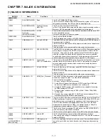
Страница 75: ...ash memories to transfer the data to CPUs and memories IC2005 VHiR24002AS 1Y 2K bit E2PROM This is a 2Kbit 2 wire I2C bus type serial EEPROM that can be pro grammed electrically This IC stores the menu data and the adjustment value data of adjustment process mode etc The data is given out by commands from the main microprocessor IC1504 VHiSii9387 1Q HDMI_Port_Processor The SiI9387 HDMI port proces...

Страница 76: ...LC 52 60LE830E RU 831E S 833E 7 2 M E M O ...

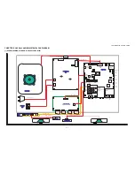
Страница 77: ...㪌㪋 㪉㩷㩷㩷㪈 㪈 㪊 䇼㪧㪣䇽 㪧㪉㪍㪇 㪚㪠㩷㪺㪸㫉㪻㩷㫊㫃㫆㫋 㪪㪚㪋㪋㪇㪈 㪫㪬㪈㪈㪇㪉 㪘㫅㪸㫃㫆㪾㪆 㪛㪭㪙㪄㪫㪆㪚㪆㪪㪆㪪㪉 㪪㫀㩷㪫㫌㫅㪼㫉 㪟㪛㪤㪠㪉㪆㪧㪚 㪘㫌㪻㫀㫆 㪡㪌㪇㪈 㪣㪘㪥 㪡㪐㪌㪇㪈 㪟㪛㪤㪠㪈 㪪㪚㪈㪌㪇㪊 㪟㪛㪤㪠㪉 㪪㪚㪈㪌㪇㪉 㪟㪛㪤㪠㪊 㪪㪚㪈㪌㪇㪈 㪬㪪㪙㪈 㪡㪐㪌㪇㪉 㪟㪛㪤㪠㪋 㪪㪚㪈㪌㪇㪌 㪟㪧㪆㪘㫌㪻㫀㫆㩷㪦㫌㫋 㪡㪌㪇㪋 㪦㫇㫋㫀㪺㪸㫃㪦㫌㫋 㪛㪌㪉㪎 㪩㪪㪉㪊㪉㪚 㪛㪄㪪㪬㪙㩷㪐㫇㫀㫅 㪪㪚㪌㪇㪋 䇼㪩㪚䇽 㪧㪉㪇㪇㪈 䇼㪣㪮䇽 㪧㪉㪍㪇㪈 䇼㪚㪠䇽 㪧㪉㪇㪇㪎 䇼㪪㪧䇽 㪧㪉㪎㪇㪈 䇼㪧㪛䇽 㪧㪐㪍㪇 䇼㪪㪙䇽 㪧㪉㪎㪇㪉 㪜㪯㪫㪈㩿㪪㪚㪘㪩㪫 㪀 㪪㪚㪌㪇㪌 㪜㪯㪫㪉㪆㪊 㪡㪌㪇㪈 㪬㪪㪙㪉 㪡㪐㪌㪇㪋 㪬㪪㪙㪊 㪡㪐㪌㪇㪋 㪈 㪈 㪌 㪈 㪋 㪧㪚㩿㪩㪞㪙㪀 㪪㪚㪌㪇㪈 㪉㪊 㪈 㪉㪋 㪊㪛㩷㪠㪩 㪬㫅㫀㫋 㪈 㪊 㪈㩷㩷㩷...

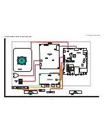
Страница 78: ...㪱 㪨㪚㪥㪮㪄㪣㪍㪇㪈㪮㪡㪨㪱 㪨㪚㪥㪮㪄㪣㪍㪇㪋㪮㪡㪨㪱 㪨㪚㪥㪮㪄㪣㪌㪐㪍㪮㪡㪨㪱 㪨㪚㪥㪮㪄㪤㪇㪈㪎㪮㪡㪨㪱 㪨㪚㪥㪮㪄㪣㪍㪈㪏㪮㪡㪨㪱 㪨㪚㪥㪮㪄㪣㪍㪉㪏㪮㪡㪨㪱 㪨㪚㪥㪮㪥 㪉㪎㪊㪊㪫㪧㪱㪱 㪨㪚㪥㪮㪥 㪉㪎㪊㪊㪫㪧㪱㪱 㪨㪚㪥㪮㪥 㪉㪎㪊㪋㪫㪧㪱㪱 㪨㪚㪥㪮㪥 㪉㪎㪊㪋㪫㪧㪱㪱 㪫㫆㩷㪣㪚㪛㩷㪤㪦㪛㪬㪣㪜 㪤㪘㪠㪥㩷㪬㫅㫀㫋 㪈 㪌 㪈 㪋㪈 㫄㫀㪺㫉㫆㩷㪪㪛 㪪㪚㪏㪋㪌㪋 㪉㩷㩷㩷㪈 㪈 㪊 䇼㪧㪣䇽 㪧㪉㪍㪇 㪚㪠㩷㪺㪸㫉㪻㩷㫊㫃㫆㫋 㪪㪚㪋㪋㪇㪈 㪟㪛㪤㪠㪉㪆㪧㪚 㪘㫌㪻㫀㫆 㪡㪌㪇㪈 㪣㪘㪥 㪡㪐㪌㪇㪈 㪟㪛㪤㪠㪈 㪪㪚㪈㪌㪇㪊 㪟㪛㪤㪠㪉 㪪㪚㪈㪌㪇㪉 㪟㪛㪤㪠㪊 㪪㪚㪈㪌㪇㪈 㪬㪪㪙㪈 㪡㪐㪌㪇㪉 㪟㪛㪤㪠㪋 㪪㪚㪈㪌㪇㪌 㪟㪧㪆㪘㫌㪻㫀㫆㩷㪦㫌㫋 㪡㪌㪇㪋 㪦㫇㫋㫀㪺㪸㫃㪦㫌㫋 㪛㪌㪉㪎 㪩㪪㪉㪊㪉㪚 㪛㪄㪪㪬㪙㩷㪐㫇㫀㫅 㪪㪚㪌㪇㪋 䇼㪩㪚䇽 㪧㪉㪇㪇㪈 䇼㪣㪮...

Страница 79: ... 㪚㪠㩷㪺㪸㫉㪻㩷㫊㫃㫆㫋 㪪㪚㪋㪋㪇㪈 㪫㪬㪈㪈㪇㪉 㪘㫅㪸㫃㫆㪾㪆 㪛㪭㪙㪄㪫㪆㪚㪆㪪㪆㪪㪉 㪪㫀㩷㪫㫌㫅㪼㫉 㪟㪛㪤㪠㪉㪆㪧㪚 㪘㫌㪻㫀㫆 㪡㪌㪇㪈 㪣㪘㪥 㪡㪐㪌㪇㪈 㪟㪛㪤㪠㪈 㪪㪚㪈㪌㪇㪊 㪟㪛㪤㪠㪉 㪪㪚㪈㪌㪇㪉 㪟㪛㪤㪠㪊 㪪㪚㪈㪌㪇㪈 㪬㪪㪙㪈 㪡㪐㪌㪇㪉 㪟㪛㪤㪠㪋 㪪㪚㪈㪌㪇㪌 㪟㪧㪆㪘㫌㪻㫀㫆㩷㪦㫌㫋 㪡㪌㪇㪋 㪦㫇㫋㫀㪺㪸㫃㪦㫌㫋 㪛㪌㪉㪎 㪩㪪㪉㪊㪉㪚 㪛㪄㪪㪬㪙㩷㪐㫇㫀㫅 㪪㪚㪌㪇㪋 䇼㪩㪚䇽 㪧㪉㪇㪇㪈 䇼㪣㪮䇽 㪧㪉㪍㪇㪈 䇼㪚㪠䇽 㪧㪉㪇㪇㪎 䇼㪪㪧䇽 㪧㪉㪎㪇㪈 䇼㪧㪛䇽 㪧㪐㪍㪇 䇼㪪㪙䇽 㪧㪉㪎㪇㪉 㪜㪯㪫㪈㩿㪪㪚㪘㪩㪫 㪀 㪪㪚㪌㪇㪌 㪜㪯㪫㪉㪆㪊 㪡㪌㪇㪈 㪬㪪㪙㪉 㪡㪐㪌㪇㪋 㪬㪪㪙㪊 㪡㪐㪌㪇㪋 㪈 㪈 㪌 㪈 㪋 㪧㪚㩿㪩㪞㪙㪀 㪪㪚㪌㪇㪈 㪉㪊 㪈 㪉㪋 㪊㪛㩷㪠㪩 㪬㫅㫀㫋 㪈 㪊 㪈㩷㩷㩷㪍 䇼㪩㪘䇽 䇼㪩㪘䇽 1 2 㪈㩷㩷㪊 㪜...

Страница 80: ...㪏㪮㪡㪨㪱 㪨㪚㪥㪮㪄㪣㪍㪇㪇㪮㪡㪨㪱 㪨㪚㪥㪮㪄㪣㪍㪈㪇㪮㪡㪨㪱 㪨㪚㪥㪮㪄㪣㪍㪈㪊㪮㪡㪨㪱 㪨㪚㪥㪮㪄㪣㪌㪏㪎㪮㪡㪨㪱 㪨㪚㪥㪮㪄㪤㪇㪈㪏㪮㪡㪨㪱 㪨㪚㪥㪮㪄㪣㪍㪉㪇㪮㪡㪨㪱 㪨㪚㪥㪮㪄㪣㪍㪉㪐㪮㪡㪨㪱 㪨㪚㪥㪮㪥 㪉㪎㪊㪈㪫㪧㪱㪱 㪨㪚㪥㪮㪥 㪉㪎㪊㪈㪫㪧㪱㪱 㪨㪚㪥㪮㪥 㪉㪎㪊㪉㪫㪧㪱㪱 㪨㪚㪥㪮㪥 㪉㪎㪊㪉㪫㪧㪱㪱 㪫㫆㩷㪣㪚㪛㩷㪤㪦㪛㪬㪣㪜 㪤㪘㪠㪥㩷㪬㫅㫀㫋 㪈 㪌 㪈 㪋 㪈 㫄㫀㪺㫉㫆㩷㪪㪛 㪪㪚㪏㪋㪌㪋 㪉㩷㩷㩷㪈 㪈 㪊 䇼㪧㪣䇽 㪧㪉㪍㪇 㪚㪠㩷㪺㪸㫉㪻㩷㫊㫃㫆㫋 㪪㪚㪋㪋㪇㪈 㪟㪛㪤㪠㪉㪆㪧㪚 㪘㫌㪻㫀㫆 㪡㪌㪇㪈 㪣㪘㪥 㪡㪐㪌㪇㪈 㪟㪛㪤㪠㪈 㪪㪚㪈㪌㪇㪊 㪟㪛㪤㪠㪉 㪪㪚㪈㪌㪇㪉 㪟㪛㪤㪠㪊 㪪㪚㪈㪌㪇㪈 㪬㪪㪙㪈 㪡㪐㪌㪇㪉 㪟㪛㪤㪠㪋 㪪㪚㪈㪌㪇㪌 㪦㫇㫋㫀㪺㪸㫃㪦㫌㫋 㪛㪌㪉㪎 㪩㪪㪉㪊㪉㪚 㪛㪄㪪㪬㪙㩷㪐㫇㫀㫅 㪪㪚㪌㪇㪋 䇼㪩㪚䇽 㪧㪉㪇㪇㪈 䇼㪣...

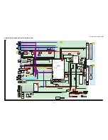
Страница 81: ...L D0 D7 N_TUN_SAT_RST LR Component CVBS LR CVBS1_IN CVBS1_IN_L R CVBS1_IN_L R 6 AUDIO_MUTE SCART SC505 SC Y_CVBS2_IN RED1 C1 GREEN1 BLUE1 SC1_IN_L R SC1_V_OUT TUNER_L R_OUT Disclete Mute Q502 SLOWSW1 SC1FSW IC510 CAPLESS VIDEO AMP with LPF NJW1351B IC507 Select MM1507XN 5 5V CVBS_O ut AMP HOP TUNER_OUTL R N_PER_RST AMP_PROTECT IC2706 OpAMP NJM4565V 13V IC2704 HP AMP AK4201EU 5V VSYNC ILL_LED1 2 3 ...

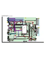
Страница 82: ...CVBS1_IN CVBS1_IN_L R CVBS1_IN_L R 6 AUDIO_MUTE SCART SC505 SC Y_CVBS2_IN RED1 C1 GREEN1 BLUE1 SC1_IN_L R SC1_V_OUT TUNER_L R_OUT Disclete Mute Q502 SLOWSW1 SC1FSW IC510 CAPLESS VIDEO AMP with LPF NJW1351B IC507 Select MM1507X 5 5V CVBS_O ut AMP HOP TUNER_OUTL R N_PER_RST AMP_PROTECT IC2706 OpAMP NJM4565V 13V IC2704 HP AMP AK4201EU 5V VSYNC ILL_LED1 2 3 PANEL_O CVBS CI Card IC4402 CI Cont DTB T C ...

Страница 83: ...bject to change without notice LC 52 60LE830E RU 830E S 833E PartsGuide 1 PRINTED WIRING BOARD ASSEMBLIES 2 LCD PANEL MODULE UNIT 3 CABINET PARTS LC 52LE830E RU 831E S 833E 4 CABINET PARTS LC 60LE830E RU 831E S 833E 5 SUPPLIED ACCESSORIES PACKING PARTS LC 52LE830E RU 831E S 833E 6 SUPPLIED ACCESSORIES PACKING PARTS LC 60LE830E RU 831E S 833E 7 SERVICE JIGS USE FOR SERVICING CONTENTS No S81T252LE83...

Страница 84: ...RATION Unit N DUNTKF770FM51 AP P ICON Unit N RUNTKA869WJQZ AZ P TOUCH SENSOR Unit N RUNTKA819WJQZ AU P 3D IR TRANSMITTER Unit N RUNTKA795WJQZ N P POWER SUPPLY Unit LC 50LE830E RU 831E S 833E N RUNTKA799WJN1 N P POWER SUPPLY Unit LC 60LE830E RU 831E S 833E N RUNTK4909TPYX N P LCD CONTROL Unit LC 50LE830E RU 831E S 833E N RUNTK4909TPYN N P LCD CONTROL Unit LC 60LE830E RU 831E S 833E 2 LCD PANEL MODU...

Страница 85: ...11 3 11 11 23 22 21 21 30 8 30 30 30 30 16 30 1 4 1 5 1 2 1 6 1 3 1 1 1 42 35 39 27 39 37 47 32 15 1 8 1 8 1 9 68 54 53 54 8 64 24 72 24 24 24 24 24 55 1 7 MAIN Unit PD F A C SB POWER SUPPLY Unit D PD E SB SP LW PL IR CI 52 LCD Panel Module Unit B E D F C LCD Control Unit LW PL G H TK TK RA Touch Sensor Unit CI ICON Unit R C Operation Unit RA 3D IR TRANSMITER Unit IR G H SP A 49 50 52 59 ...

Страница 86: ...P06WS0 AA P Screw x36 25 GCOVHA137WJSA AB P Vesa Hole Cover x4 26 GCOVAD969WJ1A P AC Cord Cover 27 GCOVAD973WJ1A P Bottom Cover 29 LANGKD124WJM1 BD P Stand T CON Angle 30 LANGKD127WJFW AD P Fixing Metal Angle x12 31 LHLDWA303WJKA AE N P Cable Clamp 32 PSPAZC062WJKZ AG P Spacer 33 QACCKA055WJPZ AQ P AC Cord for LC 52LE830E 831S 833E 33 QACCBA106WJPZ P AC Cord for LC 52LE831E 35 QCNW L600WJQZ AL N P...

Страница 87: ...23 11 30 30 30 15 30 44 16 1 1 1 7 1 3 1 4 1 2 1 35 43 40 40 37 33 67 1 8 1 9 1 9 1 5 71 66 57 58 24 24 50 24 24 24 24 53 52 51 24 74 69 70 71 68 62 65 43 59 F G A C SB POWER LED Drive Unit D PD SB PD MAIN Unit E SP LW PL TK IR CI LCD Control Unit 60 LCD Panel Module Unit B F D E C LW PL H G TK RA Touch Sensor Unit 3D IR TRANSMITTER Unit IR R C Operation Unit RA CI ICON Unit H SP A 49 61 ...

Страница 88: ... P VESA Hole Cover x4 26 GCOVAD969WJ1A P AC Cord Cover 29 LANGKD126WJM1 P Stand T CON Angle 30 LANGKD127WJFW AD P Fixing Metal Angle x14 32 LHLDWA303WJKA AE P Cable Clamp 33 PSPAZC062WJKZ AG P Spacer 34 QACCKA055WJPZ AQ P AC Cord for LC 60LE830E 830RU 833E 34 QACCBA106WJPZ P AC Cord for LC 60LE831E 35 QCNW L600WJQZ AL N P Connecting Cord RA KEY R C 36 QCNW L610WJQZ AL N P Connecting Cord CI MAN EM...

Страница 89: ... X1 X6 X7 X8 X9 S5 S5 S5 S2 Operation manual Remote control AAA size battery Cable Clamp X14 X2 X1 X17 X12 X4 X10 X20 Guarantee Card X3 Wireless LAN USB adapter X13 USB memory X5 SAFETY SHEET X6 WEEE SHEET X7 Wifi SHEET X8 DONGLE SHEET X9 Skype SHEET X19 GOST SHEET X21 GUARANTEE AQUOS S13 S13 X5 X10 X19 X20 X21 X4 X12 X13 S12 X18 GOST SHEET S14 X3 ...
Страница 90: ...GA959WJSA P Remote control Unit for LC 52LE833E X19 TCAUZA482WJZZ N P GOST SHEET for LC 52LE830RU X20 TGAN B651WJZZ P GUARANTEE for LC 52LE830RU X20 TGAN A801WJN1 P GUARANTEE for LC 52LE831E X21 TGAN A802WJN1 P GUARANTEE AQUOS for LC 52LE831E S1 SPAKCF964WJZZ CARTON BOX NOT REPLACEMENT ITEM S2 SPAKCF965WJZZ P CASE BOTTOM NOT REPLACEMENT ITEM S3 SPAKPB766WJZZ HOSO PP NOT REPLACEMENT ITEM S4 SPAKXD1...

Страница 91: ... X14 X1 S5 S5 S2 S5 S12 S12 Operation manual Remote control AAA size battery Cable Clamp X14 X2 X1 X17 X12 X4 X10 X20 Guarantee Card X3 Wireless LAN USB adapter X13 USB memory X5 SAFETY SHEET X6 WEEE SHEET X7 Wifi SHEET X8 DONGLE SHEET X9 Skype SHEET X19 GOST SHEET X21 GUARANTEE AQUOS S8 X6 X7 X8 X9 X5 X10 X19 X20 X21 X4 X12 X13 S11 S13 X3 ...

Страница 92: ...for LC 60LE831E S1 SPAKCG378WJZZ N CARTON BOX NOT REPLACEMENT ITEM S2 SPAKCG379WJZZ N P CASE BOTTOM NOT REPLACEMENT ITEM S4 SPAKXD413WJZZ N AD PAD_TOP EPS NOT REPLACEMENT ITEM S5 SPAKXD414WJZZ N AD PAD_BTM EPS NOT REPLACEMENT ITEM S6 SPAKPB702WJZZ STAND MAT BASE NOT REPLACEMENT ITEM S7 SPAKPB695WJZZ N MIRROR MAT SUPP NOT REPLACEMENT ITEM S8 SSAKAA111WJZZ P_SACKS B5 NOT REPLACEMENT ITEM S9 SPAKPB75...

Страница 93: ...LC 52 60LE830E RU 831E S 833E ...

Страница 94: ...blication may be reproduced stored in a retrieval system or transmitted in any from or by any means electronic mechanical photocopying recording or otherwise without prior written permission of the publisher SHARP CORPORATION AV Systems Group CS Promotion Center Yaita Tochigi 329 2193 Japan Aug 2011 SH DS ...

Отзывы: