Sharp Aquos LC-37HT3U Скачать руководство пользователя страница 2

LC-37HT3U/LC-37M43U

 i

LC-37HT3U

Service Manual


OUTLINE AND ADJUSTMENT
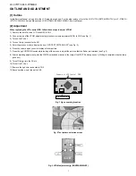
[1] Outline

In this Service Manual, only parts in the LCD module are shown. For the other points, refer to the LC-37HT3U (S97P6LC32HT3U) or LC-37M43U
(S77L7LC32M43U) Service Manual and LC-32/37D42U (S06X9LC32D42U) Service Manual.

[2] Adjustment

When replacing the LCD control PCB, follow these steps to adjust VCOM.

1) Remove the wire from the LCD control PCB CN3.

2) Connect a wire of the VCOM adjustment jig (electronic volume adjustment BOX) to CN3 (see Fig. 1).

3) Turn on the TV set.

4) Turn on the jig (connect to the AC).

5) Enter the process mode to display the item “LCD TEST PATTERN OFF” (see Fig. 2).

6) Press the volume up key once to display a flicker pattern.

7) Press the jig's UP/DOWN switch while looking at the screen to adjust the point so that the flicker is minimized (see Fig. 3).

8) After completing adjustment, press the WRITE switch and make sure the lamp of the WRITE button goes out. (Writing is complete when the lamp

goes out.)

9) Turn off the jig (turn the AC off).

10)Turn off the TV set.

11)Remove the jig’s wire connected to CN3.

12)Reconnect the wire of the set to CN3.

Fig. 1 Jig connecting location

Fig. 2 Test pattern selection screen

Fig. 3 VCOM adjustment jig (RUNTZA059WJZZ)

CN3

Jig connection

'ZCORNGQH.%&%QPVTQN29$

Содержание Aquos LC-37HT3U

Страница 1: ...notice TopPage LC 37HT3U LC 37M43U LCD COLOR TELEVISION LC 37HT3U LC 37M43U MODELS SUPPLEMENT In the interests of user safety Required by safety regulations in some countries the set should be restored to its orig inal condition and only parts identical to those specified should be used In this Service Manual only parts in the LCD module are shown For the other points refer to the LC 37HT3U S97P6L...

Страница 2: ...et 4 Turn on the jig connect to the AC 5 Enter the process mode to display the item LCD TEST PATTERN OFF see Fig 2 6 Press the volume up key once to display a flicker pattern 7 Press the jig s UP DOWN switch while looking at the screen to adjust the point so that the flicker is minimized see Fig 3 8 After completing adjustment press the WRITE switch and make sure the lamp of the WRITE button goes ...

Страница 3: ... ones for maintaining the safety and performance of the set This document has been published to be used for after sales service only The contents are subject to change without notice LC 37HT3U LC 37M43U PartsGuide 1 LCD MODULE Assembly CONTENTS No S97Q9LC37HT3U LCD COLOR TELEVISION LC 37HT3U LC 37M43U MODELS LC 37HT3U LC 37M43U ...

Страница 4: ...LC 37HT3U LC 37M43U 2 1 LCD MODULE Assembly 1 9 20 14 11 15 16 17 16 15 18 19 12 13 10 21 22 30 25 24 31 23 30 30 30 29 27 27 27 27 28 3 2 4 5 7 8 4 26 6 ...

Страница 5: ... J Lamp Holder Bottom A 13 LHLDZ3415TPZZ AE N J Lamp Holder Bottom B 14 LHLDZA709WJKZ AC J Sheet Holder x6 15 LHLDZ3410TPZZ AD N J Lamp clip A x2 16 LHLDZ3411TPZZ AD N J Lamp clip B x2 17 LHLDZ3614TPZZ AD N J Lamp clip C x2 18 PREFL2390TPZZ AX N J Reflection Mirror 19 CANGK3715TP01 BL N J Chassis 20 PZETE3991TPZZ AN N J Insulation Sheet 21 RDENC2300TPZA BQ N J INVERTER Unit 22 LANGK3716TPZZ AP N J...

Страница 6: ...tion may be reproduced stored in a retrieval system or transmitted in any from or by any means electronic mechanical photocopying recording or otherwise without prior written permission of the publisher SHARP CORPORATION AV Systems Group CS Promotion Center Yaita Tochigi 329 2193 Japan TQ2322 S YK DS ...

Отзывы: