[3]
INSTALLING THE OPTIONAL
PRINTER UPGRADE KIT
To install the printer board and memory, be sure to follow the
precautions below.
●
Be sure to turn off this machine and your computer and
remove the power cord before starting installation. If not, an
electric shock or injury may result.
●
Do not touch the chips, circuits, and connectors on the
printer board and memory board directly with your hands.
Doing so may damage them through static electricity.
●
Discharge the static electricity in your body by touching
a grounded metal part before starting installation.
●
To protect the printer board and memory from static
damage, remove them from protective bags just before start-
ing work.
●
Do not touch any object which easily generates static
electricity (such as a computer display) with your hand.
●
Do not subject the printer board and memory to undue
shock.
●
Do not put the printer board or memory in a location
which easily generates static electricity (such as on a
carpet).
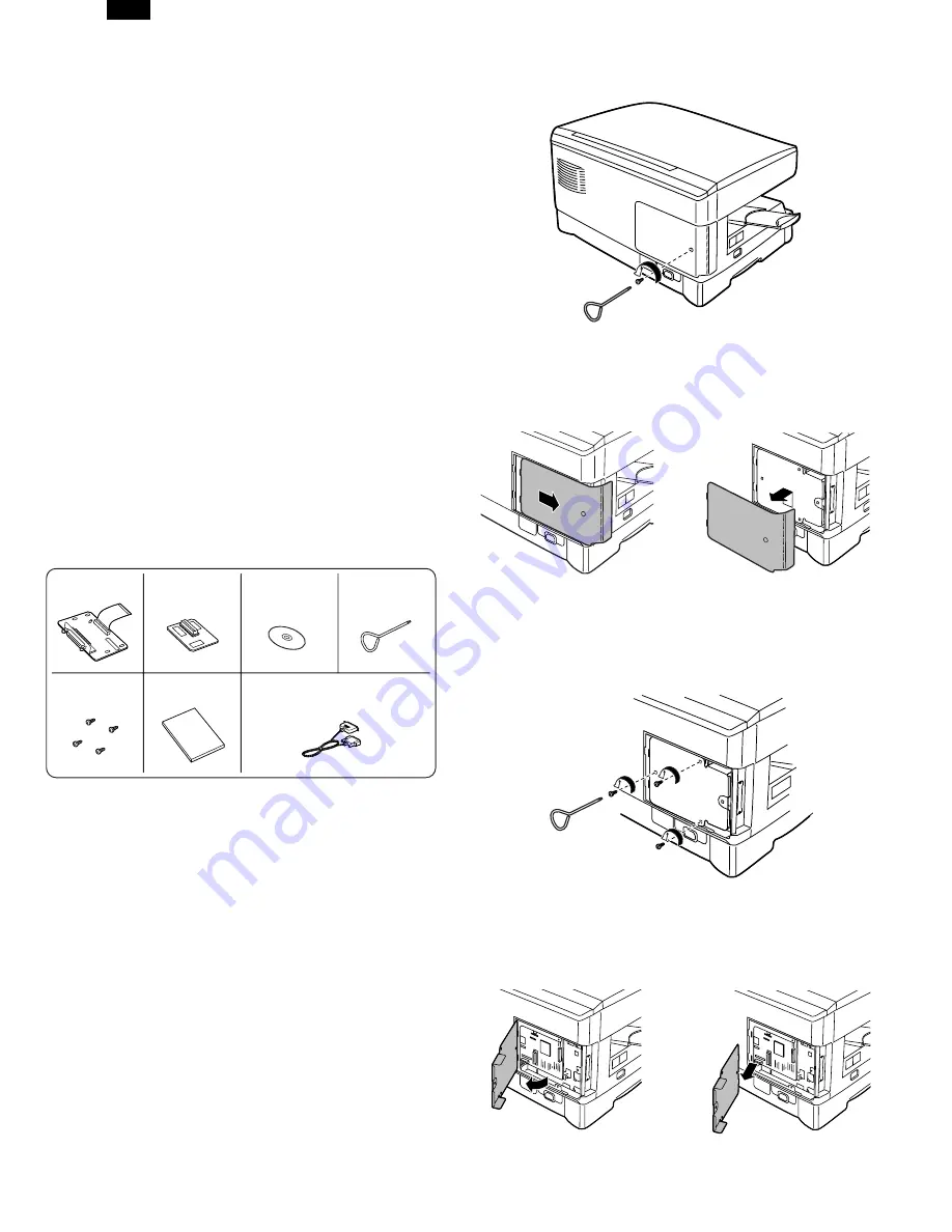
1. Checking packed components and acces-
sories
Open the carton and check if the following components and ac-
cessories are included.
∗
In some models, the memory has been already installed in
the machine and is not supplied in the printer upgrade kit
(AL-10PK).
2. Removing the cabinet cover and board
cover
1) Ensure that the power switch on the copier is in the off posi-
tion. Remove the power cord from the power cord socket at
the rear of the copier.
2) Remove the screw from the cabinet cover at the rear side
of the machine using the supplied screwdriver.
3) Slide the cabinet cover in the direction indicated by the
arrow and pull the cover while raising it a little to remove it.
4) Remove the three screws from the board cover.
5) Open the board cover in the direction indicated by the arrow
and then remove it.
Interface cable ... 1
(for IBM PC/AT or compatible computers)
Operation manual ... 1
Printer driver
(CD-ROM) ... 1
Screwdriver ... 1
Screws ... 4
Memory ... 1
∗
Printer board ... 1
AL-1041
3-1
Содержание AL-1010 - B/W Laser - Copier
Страница 9: ... 6 CIRCUIT DIAGRAM GDI PWB AL 1041 6 1 ...
Страница 10: ...GDI MEMORY PWB 4MB AL 1041 6 2 ...
Страница 11: ...GDI MEMORY PWB 6MB AL 1041 6 3 ...


