18
AH-N45DP2
AU-N45DP2
AH-N56DP2
AU-N56DP2
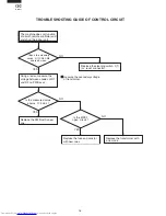
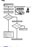
The room is not cooled at all
or not cooled.
The compressor does not operate.
Measure resistances of TH1 and TH2.
Push the button "AUX." on
the indoor unit, for more than 5 sec.
Is the voltage
between terminal "N" and
"1" of the terminal board the
power supply voltage ?
Are the resistances
conformed Fig. 1 ?
Replace the thermistor ass'y
with a new one.
NO
YES
YES
NO
Replace the PWB ass'y with a new one.
Fig. 1
Using a tester, measure voltage at
the terminals on the terminal board.
100
80
60
40
20
0
-10
0
10
20
30
40
Resistance
Thermistor
Room temperature
Heat exchange
Color
Yellow
Orange
To measure the resistance, first remove
the connector as shown at right.
Room temperature
thermistor TH1
Tester
Connector
No. 3 to 4
No. 1 to 2
Fig. 1 Temperature properties of indoor thermistors
K
Heat exchange thermistor
TH2 (orange)
25
°
C resistance 15 K
Room temperature
thermistor TH1 (yellow)
25
°
C resistance 10 K
Heat exchange
thermistor TH2
Tester
4
1
CN4
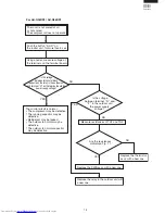
The control circuit is normal.
The compressor may be defective.
The running capacitor may be
defective.
Refrigerant may be leaked.
The outdoor fan motor may be
defective.
The outdoor fan motor capacitor
may be defective.

