


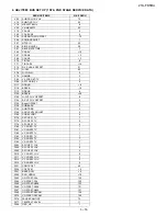


21K-FD5RU
3 – 20
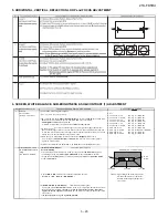
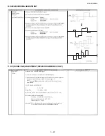
5. HORIZONTAL, VERTICAL, DEFLECTION LOOP and FOCUS ADJUSTMENT
6. SCREEN, WHITE BALANCE, SUB-BRIGHTNESS & SUB-CONTRAST (1) ADJUSTMENT
NO ADJUSTMENT POINT
ADJUSTMENT CONDITION / PROCEDURE
WAVEFORM OR OTHERS
1
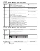
SCREEN
(1) In window pattern signal condition
ADJUSTMENT
Note 1:
(I2C BUS CONTROL)
(2) Go to service mode, then select V00.
R-CUTOFF (R-C) UP
RC key "1" (HEX 80)
R-CUTOFF (R-C) DOWN
RC key "4" (HEX 20)
(3) By pressing R/C key
S-Mute (Hex E8)
,
R-D
auto switch to
31
,
B-D
auto switch to
31
,
G-CUTOFF (G-C) UP
RC key "2" (HEX 40)
R-C
auto switch to
95
,
G-C
auto switch to
95
,
B-C
auto switch to
95
,
G-CUTOFF (G-C) DOWN
RC key "5" (HEX A0)
Sub-brightness V06
auto switch to
75.
B-CUTOFF (B-C) UP
RC key "3" (HEX C0)
Y-mute & Vertical off, screen will be in
vertical cut-off
condition
B-CUTOFF (B-C) DOWN
RC key "6" (HEX 60)
R-DRIVE (R-D) UP
RC key "7" (HEX E0)
(4) Adjust the Screen so that cut-off line appear in low bright, then judge that whether
R-DRIVE (R-D) DOWN
RC key "Flashback" (HEX E4)
the cut-off line appear in Red or Green or Blue color, in this condition between R-C &
B-DRIVE (B-D) UP
RC key "8" (HEX 10)
G-C & B-C, fix the data of the color appear in cut-off line and adj the other two cut-off
B-DRIVE (B-D) DOWN
RC key "0" (HEX 50)
data (Note 1) so that cut-off line color become white.
(5)Turn the screen VR of FBT so that cut-off line just
disappea
r and use R/C
by pressing key
S-Mute (Hex E8)
to
disable
the Y-mute & V-cut so that picture
appear in normal mode.
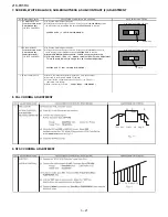
2 WHITE BALANCE ADJ
(1)WHITE (HIGH BEAM)
( In Window Pattern Signal)
(to be done after screen
For 21K-FD5RU
adj)
First use Minolta Color Analyzer CA100, let the gun point at
Dark White
position
(I2C BUS CONTROL)
(as drawing attach), Adj
V06
until
LUMINANCE Y
become
5 cd/m2
, then let
the gun point at
White
position ( as drawing attach), Adj
V04
until
LUMINANCE Y
White
Dark
become:
200 cd/m2.
White
5.5% IRE
9.5% IRE
Adj the
R-D
&
B-D
until the axis of color temperature become
*Note :
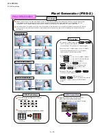
Signal using W/B Pattern Generator
X=300, Y=310
7500
o
K (21K-FD5RU )
SX-1006 (IWATSU) or equivalent.
Window Pattern Signal output level
are as above:
(2) DARK WHITE (LOW BEAM)
(In Window Pattern Signal)
Let the gun point at
Dark White
position, if the color temperature data shift away from
the data adjusted in
step 1
, adjust
R-C, G-C & B-C but between them, first color
appears in Screen adj item 1)-4 is fixed
, adj the other two so that to obtain the similar
axis as above.
** Repeat step 1 & 2 to get a regulated position
WINDOW PATTERN SIGNAL
50% IRE
( 6 )After screen Adjustment, adjust R-D to 63 and B-D to 63 for White Balance Adj.
Содержание 21K-FD5RU
Страница 21: ...21K FD5RU 3 18 2 ADJUSTMENT 1 PIF ADJUSTMENT CHECKING 2 PURITY ADJUSMENT ...
Страница 22: ...21K FD5RU 3 19 3 CONVERGENCE ADJUSTMENT 4 H VCO VIF VCO S TRAP for ADJUSTMENT ...
Страница 27: ...21K FD5RU 3 24 15 FUNCTION OPERATION CHECKING 2 VIDEO AUDIO CONTINUED ...
Страница 29: ...21K FD5RU 3 26 19 SHOCK TEST CHECKING 20 ROM CORRECTION CHECKING N O 0 90 0 90 584 N O 0 90 0 90 584 ...
Страница 58: ...21K FD5RU 5 1 TV 21K FD5RU Service Manual 21K FD5RU Market E CHAPTER 5 TROUBLE SHOOTING 1 TROUBLE SHOOTING ...
Страница 59: ...21K FD5RU 5 2 TROUBLE SHOOTING Continued pin 11 pin 13 of SC304 ...
Страница 60: ...21K FD5RU 5 3 TROUBLE SHOOTING Continued I I I I ...
Страница 62: ...21K FD5RU 7 1 CHAPTER 7 CHASSIS LAYOUT 1 CHASSIS LAYOUT A C B D E F G H 1 2 3 4 5 6 7 8 9 10 ...
Страница 64: ...21K FD5RU 8 2 10 11 12 13 14 15 16 17 18 19 ...
Страница 66: ...21K FD5RU 8 4 4 BLOCK DIAGRAM NICAM UNIT A C B D 1 2 3 4 5 6 7 8 9 10 ...
Страница 70: ...21K FD5RU 11 2 3 SCHEMATIC DIAGRAM NICAM UNIT A C B D 1 2 3 4 5 6 7 8 9 10 ...
Страница 71: ...21K FD5RU 11 3 4 SCHEMATIC DIAGRAM MAIN UNIT A C B D E F G H 1 2 3 4 5 6 7 8 9 10 ...
Страница 72: ...21K FD5RU 11 4 10 11 12 13 14 15 16 17 18 19 ...
Страница 74: ...21K FD5RU 12 2 10 11 12 13 14 15 16 17 18 19 ...
Страница 75: ...21K FD5RU 12 3 2 MAIN UNIT Chip Parts Side A C B D E F G H 1 2 3 4 5 6 7 8 9 10 ...
Страница 76: ...21K FD5RU 12 4 10 11 12 13 14 15 16 17 18 19 ...
Страница 96: ...www s manuals com ...


