4
21HS-50H
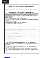
IMPORTANT SERVICING NOTES
Only qualified service personnel are allowed to carry out maintenance and repair of this receiver.
SERVICING OF HIGH VOLTAGE SYSTEM AND CRT
It is important that the static charge is removed from the high voltage system when carrying out work
on the receiver. This can be achieved by connecting a 10K resistor (with a suitably insulated lead) from
the CRT cavity connector to the CRT ground tag. This must be carried out with the AC supply discon-
nected from the receiver.
Note the following:
•
The CRT in this receiver employs Integral Implosion Protection.
•
If the CRT has to be changed it MUST be replaced with the correct type for continued safe
working
•
DO NOT lift the CRT by its neck.
•
When handing the CRT, ensure that shatterproof goggles are worn.
•
Ensure that the CRT is discharge before handling.
X-RAY
This receiver is designed to keep any x-ray emission to an absolute minimum. Some fault conditions
and servicing procedures may produce potentially hazardous x-ray radiation levels. This is a problem
when in close proximity to the receiver for long periods of time. To reduce any risks associated with
this, please observe the following precautions:
1. When undertaking any servicing on this chassis, DO NOT increase the EHT to more than 30.5 KV,
(at a instantaneous beam current of 1300
µΑ).
2. Ensure that during normal operation the EHT does not exceed 25.0 KV
±
1.5KV (at a beam current of
1100
µΑ).
This level has been preset in the factory. Always check that this level has not been ex-
ceeded after carrying out any repair on the receiver.
3. DO NOT replace the CRT with any other type than that specified in the parts listing as this may
cause excessive x-ray radiation.
BEFORE RETURNING THE RECEIVER TO THE CUSTOMER
In addition to the above checks, the following should also be carried out before returning the receiver
to the customer.
1. Inspect all the leads to ensure that they are dressed correctly and that they are not obstructed or
pinched by any other parts.
2. Ensure that all protective devices are in good condition. These will include nonmetallic control
knobs, insulating fish papers, cabinets backs, compartment covers or shields, mechanical insulators,
etc.
Содержание 21HS-50H
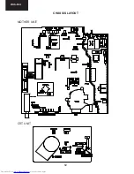
Страница 12: ...12 21HS 50H CHASSIS LAYOUT MOTHER UNIT CRT UNIT ...
Страница 27: ...27 21HS 50H ...
Страница 28: ...28 21HS 50H Page 29 1 I H G F E D C B A 2 3 4 5 6 7 SCHEMATIC DIAGRAM OF MOTHER UNIT F7340N4 01 Version ...
Страница 30: ...30 21HS 50H SCHEMATIC DIAGRAM OF MOTHER UNIT F7340N4 01 Version 8 9 10 11 12 13 14 I H G F E D C B A Page 29 ...
Страница 31: ...31 21HS 50H SCHEMATIC DIAGRAM OF CRT F7341N0 00 Version 1 I H G F E D C B A 2 3 4 5 6 7 ...
Страница 32: ...32 21HS 50H CRT UNIT BLOCK DIAGRAM 1 I H G F E D C B A 2 3 4 5 6 7 ...
Страница 33: ...33 21HS 50H MOTHER UNIT BLOCK DIAGRAM 1 I H G F E D C B A 2 3 4 5 6 7 ...
Страница 43: ...43 21HS 50H NOTES ...


